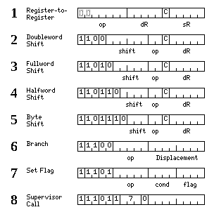
The instructions to be described in this section have the formats shown in this diagram:
These instructions are 18 bits in length.
The short instructions do not include memory-reference instructions, or the subroutine jump instruction. However, while the set of 18-bit instructions is therefore not complete in itself, it is sufficient that a large proportion of the instructions in a program could be 18-bit instructions.
From two to fifteen consecutive instructions of this type may be embedded in a longer instruction, following the format below:
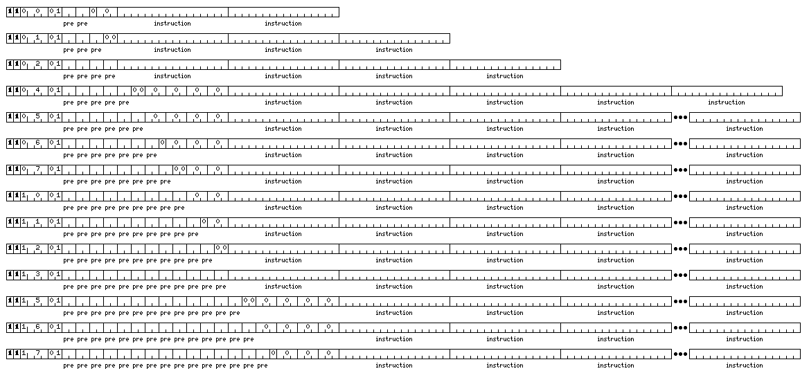
The lengths of these instructions, and the numbers of embedded 18-bit instructions within them, are:
Length      Number of Embedded Instructions

 48          2
 64          3
 80          4
112          5
128          6
144          7
160          8
176          9
192         10
208         11
224         12
256         13
272         14
288         15
Line 1, in the topmost diagram of the formats of the 18-bit embedded instructions themselves gives the format of the operate instructions. Integer instructions reference the integer registers, and floating-point instructions reference the floating-point registers, as might be expected.
There are 96 possible opcodes, as the first two bits of an opcode may not be both 1, as these combinations are reserved for other 24-bit instructions.
The opcodes (with the first four bits appearing along the top of the chart, and the last three bits appearing on the right) are:
   0     10     20     30     40     50     60     70    100    110    120    130
0000   0001   0010   0011   0100   0101   0110   0111   1000   1001   1010   1011

       IB     DEUH   IH     DEU    I      DEUL   SW     SWM    SWF    SWD    SWQ    000 0
CB     XB     CH     XH     C      X      CL     XL     CM     CF     CD     CQ     001 1
LB     ULB    LH     ULH    L      UL     LL     SWL    LM     LF     LD     LQ     010 2
STB    DUB    STH    DUH    ST     DU     STL    DUL    STM    STF    STD    STQ    011 3
AB     NB     AH     NH     A      N      AL     NL     AM     AF     AD     AQ     100 4
SB     OB     SH     OH     S      O      SL     OL     SM     SF     SD     SQ     101 5
MB     SWB    MH     MEH    M      ME     ML     MEL    MM     MF     MD     MQ     110 6
DB     SWH    DH     DEH    D      DE     DL     DEL    DM     DF     DD     DQ     111 7
The different instructions are:
For integer types:
M     MULTIPLY            Multiply the contents of the source and destination locations, placing the
                          least significant part of the result of the same length as the two input
                          operands in the destination location, with sign extension if that is shorter
                          than the length of the destination register

D     DIVIDE              Divide the contents of the source location by the contents of the destination
                          location, placing the quotient in the destination location

L     LOAD                Place the contents of the source operand in the destination register;
                          if the type involved is smaller than the register, perform sign extension

ST    STORE               Fill the destination location from the least significant part of the
                          source location

A     ADD                 Add the contents of the source and destination locations, placing the
                          result in the destination location

S     SUBTRACT            Subtract the contents of the source location from those of the destination
                          location, placing the result in the source location

SW    SWAP                Exchange the contents of the source and destination locations

C     COMPARE             Subtract the contents of the source location from the contents of
                          the destination location, but with the operation modified so that
                          overflow cannot possibly result, and set the condition codes appropriately
                          without modifying the destination location

I     INSERT              Fill the least significant bits of the destination register with
                          the contents of the source location, leaving the rest of the destination
                          register unaffected

X     EXCLUSIVE OR        Perform a bitwise Exclusive OR operation between the contents of the source
                          and destination locations, placing the result in the desination location

UL    UNSIGNED LOAD       Fill the least significant bits of the destination register with
                          the contents of the source location, and clear the remaining more
                          significant bits of the destination register

DU    DIVIDE UNSIGNED     Divide the contents of the source location by the contents of the destination
                          location, considering both as unsigned integers, placing the quotient in the
                          destination location

N     AND                 Perform a bitwise Logical AND operation between the contents of the source
                          and destination locations, placing the result in the desination location

O     OR                  Perform a bitwise Logical OR operation between the contents of the source
                          and destination locations, placing the result in the desination location

ME    MULTIPLY EXTENSIBLY Multiply the contents of the source and destination locations. Take the
                          full product, as an integer having twice the size as that of the source
                          and the destination, and:
 - in the case of the halfword and integer versions of the instruction, place it in the destination
   register, with sign extension in the halfword version;
 - in the case of the long version of the instruction, place the most significannt half of the result
   in the destination register, which must be an even-numbered register, and place the least significant
   half of the result in the register following

DE    DIVIDE EXTENSIBLY   Divide a destination operand of twice the length of that indicated by the
                          instruction type (and located as the result of the MULTIPLY EXTENSIBLY
                          instruction) by the source operand; store the double length quotient
                          in the destination location (again following the MULTIPLY EXTENSIBLY
                          result placement) and the single length remainder in the next register
                          following those that are used.
                             Whenever a result is not wide enough to fill a register, sign extension
                          is performed.
                             Division is performed giving a result as if both operands were converted
                          to positive numbers before starting, with the signs then set afterwards
                          to give a correct result based on the actual signs of the operands. Thus
                          both the quotient and the remainder will be positive or zero if the dividend
                          and divisor have the same sign, and both will be negative or zero if they
                          are of opposite signs.

DEU   DIVIDE EXTENSIBLY UNSIGNED  This instruction also uses a dividend, and gives a quotient, at
                                  double the length indicated by the instruction type, while the
                                  divisor and the remainder are at the actual length the instruction
                                  type indicates; it differs by acting on unsigned integers.
The possible integer types, and the suffixes that indicate them, are:
B     BYTE      An 8-bit two's complement integer
H     HALFWORD  A 16-bit two's complement integer
      INTEGER   A 32-bit two's complement integer
L     LONG      A 64-bit two's complement integer
The integer registers are 64 bits long, to contain the longest of these types.
The available floating-point operations are SWAP, LOAD, STORE, ADD, SUBTRACT, MULTIPLY, and DIVIDE. Their functions are basically the same as those of the corresponding integer operations, except that floating-point arithmetic is performed.
The possible floating-point types for 16-bit instructions, and the suffixes that indicate them, are:
M     MEDIUM    A 48-bit floating-point number (preferably aligned on 16-bit boundaries)
F     FLOATING  A 32-bit floating-point number
D     DOUBLE    A 64-bit floating-point number
Q     QUAD      A 128-bit floating-point number
with their formats as indicated within this diagram:

Note that in the diagram, exponents for the types other than the 128-bit internal type are given as excess-126, excess-510, and excess-1022; documentation for the IEEE 754 standard, and most descriptions of it, refer to the exponents as excess-127, excess-511, and excess-1023 instead. This is because these accounts place the binary point of the mantissa in front of its first visible bit, while I place it in front of the hidden first bit to remain in accord with the convention used in most other floating-point formats that the mantissa is in the range [0.1). In the case of the 128-bit internal form, as the first bit of the mantissa is now the bit which would have been the hidden bit, since for the other forms, I had been placing the binary point in front of the hidden bit, the offset is consistent by remaining two less than a power of two; this would need to be the case even if I had used the normal convention for the exponents of the other formats.
The IEEE 754 standard for floating-point arithmetic includes new standard formats for 128-bit and 256-bit numbers. The format for 128-bit numbers shown above does not correspond to this standard, as it instead has no hidden bit, and is similar in its general plan to the 80-bit temporary real format used with the Intel 8087 math coprocessor. However, the exponent field in that temporary real format was only 15 bits in length; this format, instead, has an exponent field 20 bits in length./p>
This is because the format for the usual format for 128-bit numbers, while not corresponding to the new IEEE 754 standard, has been influenced by it; the exponent field is one bit longer than that of standard 256-bit floats, so that these 128-bit numbers will have the same size of exponent as an internal form for floating-point numbers suitable for supporting all the standard types of IEEE 754 floating-point numbers, including the new 128-bit and 256-bit ones.
Lines 2 through 5 of the diagram illustrate the shift and rotate short instructions. These are:
60x0xx  LSLLC   Logical Shift Left Long Compact
60x1xx  LSRLC   Logical Shift Right Long Compact
60x2xx  RLLC    Rotate Left Long Compact
60x3xx  ASRLC   Arithmetic Shift Right Long Compact

64x0xx  LSLC    Logical Shift Left Compact
64x1xx  LSRC    Logical Shift Right Compact
64x2xx  RLC     Rotate Left Compact
64x3xx  ASRC    Arithmetic Shift Right Compact

66x0xx  LSLHC   Logical Shift Left Halfword Compact
66x1xx  LSRHC   Logical Shift Right Halfword Compact
66x2xx  RLHC    Rotate Left Halfword Compact
66x3xx  ASRHC   Arithmetic Shift Right Halfword Compact

6700xx  LSLBC   Logical Shift Left Byte Compact
6701xx  LSRBC   Logical Shift Right Byte Compact
6702xx  RLBC    Rotate Left Byte Compact
6703xx  ASRBC   Arithmetic Shift Right Byte Compact
Logical right and left shifts insert zeroes; the arithmetic right shift inserts a copy of the existing value of the most significant bit into the leftmost position of the word so as to maintain the sign as either negative or non-negative.
An arithmetic left shift inserts zeroes into the leftmost end of a number regardless of its sign, just like a logical left shift, but it differs in that the overflow bit is set if a left shift results in a change of the sign of the value being shifted, instead of merely a carry out of that value; this difference is, however, not applicable to short instructions, as they may not alter the condition codes, not having space for a C bit.
In the 16-bit short instructions, there is no available separate region of opcode space for the rotate instructions, and so instead the arithmetic left shift is replaced by rotate left.
Line 6 of the diagram shows the branch instructions.
The displacement is an 8-bit signed value, in two's complement form, which may vary from -128 to +127. The displacement is units of 32 bits. A displacement of zero refers to the position immediately following the instruction.
The available branch instructions are:
7000xx  NOP   No Operation
7004xx  BLR   Branch if Low Raw
7010xx  BER   Branch if Equal Raw
7014xx  BLER  Branch if Low or Equal Raw
7020xx  BHR   Branch if High Raw
7024xx  BNER  Branch if Not Equal Raw
7030xx  BHER  Branch if High or Equal Raw
7034xx  B     Branch

7044xx  BM    Branch if Minus
7050xx  BZ    Branch if Zero
7054xx  BMZ   Branch if Minus or Zero
7060xx  BP    Branch if Plus
7064xx  BNZ   Branch if Not Zero
7070xx  BPZ   Branch if Plus or Zero
7074xx  BNV   Branch if No Overflow

7104xx  BL    Branch if Low
7110xx  BE    Branch if Equal
7114xx  BLE   Branch if Low or Equal
7120xx  BH    Branch if High
7124xx  BNE   Branch if Not Equal
7130xx  BHE   Branch if High or Equal
7134xx  BNC   Branch if No Carry

7140xx  BC    Branch if Carry
7144xx  BV    Branch if Overflow
The instructions from Branch if Minus to Branch if Plus or Zero are intended for use after floating-point operations or operations on signed integers. The instructions from Branch if Low to Branch if High or Equal are intended for use after operations on unsigned integers.
Line 7 of the diagram of short instructions shows how condition values that are invalid result instead in an additional category of instructions which affect the flags used for predicated instructions.
7210xx  SFC   Set Flag on Condition   Set flag to 1 if condition met; leave it unaffected otherwise
7214xx  CFC   Clear Flag on Condition Set flag to 0 if condition met; leave it unaffected otherwise
7220xx  CTF   Condition to Flag       Set flag to 1 if condition valid; set flag to 0 if condition not met
Line 8 of this diagram shows how an additional invalid condition value provides another special instruction:
7370xx SVC Supervisor Call
This instruction performs the equivalent of an interrupt from within software, allowing portions of the operating system not running in supervisor state to request services from the kernel, as well as possibly also allowing user programs to request services from the operating system.