The drawings on the previous pages illustrate the front panels of a number of old computers with front panels of varying degrees of impressiveness.
While they may look pretty, of course, the many other pages with actual photographs of these types of computer have the virtue of realism and authenticity in greater measure. For these pages to serve a truly informative purpose, they should say something about front panels, like how they worked.
Of course, about the classic style of front panel, there isn't really all that much to say.

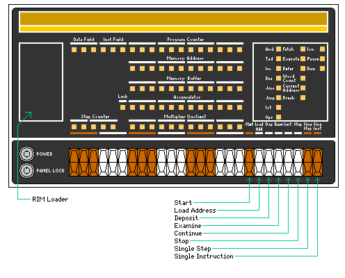
The diagram above shows the front panel from the PDP-8/I computer. This was a relatively early model of PDP-8 computer, in the first group of models to eschew discrete transistors for integrated circuits. The other model in that group was the PDP-8/L, which had a slightly faster cycle time, but which had fewer expansion options.
It was possible to expand the PDP-8/I to a configuration which would actually permit timesharing; a number of users could work with the PDP-8/I at the same time from Teletype Model 33 ASR terminals or other ASCII terminal devices. This was an impressive feat for a computer which was, architecturally, about as small and simple as a computer could get.
The computer has two switches controlled with a round key, of the high-security type used on vending machines. One turns on power to the computer, the other enables or disables the use of the switches on the front panel.
The rectangle on the left side of the console contains the RIM loader. This is a very short and simple program that reads in, from a paper tape on the console ASR teletypewriter, programs punched in a form consisting of an address immediately followed by one word to store at that address. Normally, it was only used to read in a paper tape containing the BIN loader, which read tapes in a fancier and more practical format allowing multiple consecutive words of data to follow an address.
This type of bootstrap principle is very common on computers; for example, the floppy disk drives of the Apple II computer were read by means of a short program that read four bits of data from eight bits of data on the disk in a form of group code recording, and what that program read was a longer program to use a more complicated code to obtain six bits of data from every eight bits on the disk.
Fortunately, core memory is non-volatile, so the BIN loader could be left in the computer until overwritten by an errant program. The fact that the RIM loader had to be entered by hand from the front panel, because the convenience of a bootstrap ROM was inordinately expensive at that time, of course indicates one major reason why computers had front panels.
In the row of switches on the front of the computer, the first eighteen switches could remain in the on or off position, and were used as a source from which to transfer data to the registers or memory of the computer. They were followed by eight momentary-contact switches of matching styling with the following functions:
On the right side of the panel, several lights indicate what the machine is doing.
The first column of lights, And, Tad, Isz, Dca, Jms, Jmp, Iot, and Opr simply indicate what instruction is being executed, as indicated by its three-bit opcode field.
In the second column, the Fetch light indicates the computer is retrieving data from memory, the Execute light indicates the computer is processing an instruction, and the Defer light indicates it is handling an indirect address.
Word Count, Current Address, and Break are states entered into when an I/O device is asking the computer to carry out a transfer of data to or from memory, essentially similar to DMA but mediated by the processor rather than direct.
Ion shows that interrupts are enabled; Pause is a state in the execution of input/output instructions; and Run shows that the machine is actively executing instructions.