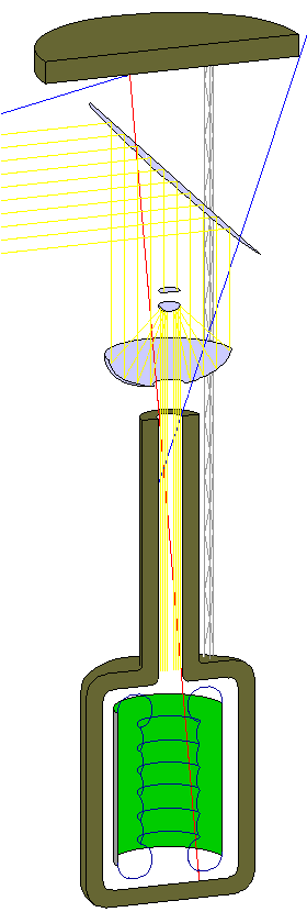

The diagram at the right is a schematic of a design for a space habitat that solves some problems that some people have claimed make the idea invalid.
A space habitat in which people will be living for a long term requires radiation shielding. Unfortunately, radiation shielding can actually make the problem of radiation in space worse instead of better, because cosmic rays (very fast moving large atomic nuclei) will produce secondary radiation when they strike thin shielding.
If the shielding is made sufficiently thick, of course, then all but a minute fraction of the cosmic rays and the secondary radiation they produce will be blocked by the shielding. After all, the Earth is located in space; if its atmosphere and magnetic field provide adequate shielding from the radiation in space for people on the ground, then a shield of equivalent thickness will provide enough protection for people in space.
Previous designs for space habitats, however, have limited the amount of radiation shielding that could be included. In some, the shielding material partakes in the rotation which produces artificial gravity for the space colonists, which means that its thickness is limited by the structural strength of the space habitat. In others, sunlight reaches the habitat through an expanse of clear glass.
The habitat design shown here makes it completely practical to use leftovers from mining to produce shielding several feet thick, or, in fact, arbitrarily thick, which surrounds the people in the habitat from absolutely all directions. Thus, if the shielding provided by thirty feet of solid rock is desired, it can be obtained. If it is desired to put a team of scientists within the heart of Jupiter's radiation belts to remotely operate a rover on one of Jupiter's moons, it could be done with this design.
Many of the ideas in this design are not new with me, of course. The use of nonrotating shielding and a 45-degree relay mirror were part of the well-known Stanford Torus design, and using a parabolic mirror to concentrate sunlight for distribution within a space settlement even predates Gerard K. O'Neill, as part of a hollowed-out asteroid proposal by Dandridge M. Cole. The paperback edition of The High Frontier shows a design by an MIT class which strongly resembles this one, as it involves both a 45-degree relay mirror, and a Cassegrain optical system to concentrate sunlight. However, that design is not identical to this one, as the shielding also serves as the ground under the habitat and rotates; another design in the book, the "Crystal Palace" or "Hatbox" design has a rotating cylinder within vacuum inside cylindrical shielding, and that is the basic scheme of the habitat area in this design. In addition to combining elements of those designs, the use of a long, narrow tube of shielding to admit sunlight, facing a slab of shielding on the far side of the mirrors is the major innovation of this design.
It is intended that the vertical axis in the diagram shall be perpendicular to the ecliptic. In this way, the incoming yellow lines, representing sunlight, are reflected by a thin flat reflector which is turned to face the sun. It is not necessary to have the habitat as a whole realigned to face the sun, with the expenditure of consumables.
A Cassegrain optical system concentrates the sunlight, so it can enter the narrow neck of a bottle-shaped shielding structure, within which the rotating cylindrical habitat is located. (Technically speaking, because the system is afocal, and therefore the secondary is also a paraboloid, it actually corresponds to the Mersenne telescope rather than the classical Cassegrain.) This too is made of thin aluminized plastic, held in the desired shape by a metal framework. Concentrating the sunlight in this way allows enough to go through to provide light for a long rotating habitat cylinder.
The diagram also shows two blue lines representing cosmic rays. The large flat disk of shielding material at the top of the diagram blocks all radiation approaching the habitat from the direction in which the neck of the bottle-shaped shielding structure points, unless it comes in at an oblique enough angle that it is unable to go all the way down the neck to the habitat. As the blue line entering from the upper right-hand corner of the diagram, which grazes the edge of the disk, and then hits the edge of the neck, illustrates.
The blue line entering from the left-hand side of the diagram hits the underside of the disk, generating secondary radiation which can enter the neck of the cylinder. As the inside of the "bottle" is in vacuum, no glass window, which, with chevron shielding, could block the secondary radiation is present. But because of the length of the neck, the secondary radiation is limited to a narrow cone in the center, which does not reach the cylindrical habitat. However, if it is desired to make the habitat longer without lengthening the neck, some areas could be reached by the secondary radiation. If, at that distance, it is still a problem, a window in the neck of the shielding material would be required.
However, as pictured, while secondary radiation from the inside of the slab won't reach the habitat, secondary radiation from cosmic rays hitting the inside of the neck will still do so. This may not be a serious hazard, but it can be completely eliminated simply by doubling the length of the neck from that shown in the diagram.
The dark blue lines on the two sides of the cylinder are not to scale, but represent the profile of a layer of reinforced clear plastic which would be used to contain the habitat's air; the lines are connected by arcs representing where segments are held together. Since the surface is made up from pieces of toruses, the "skin" of the habitat meets the shape conditions for a pressure vessel, except for the boundaries between different toruses.
As noted above, this design has borrowed some features from the Stanford Torus design. However, it is still a different design, in that it leads to a "tube" shaped cylinder rather than a "ring" shaped cylinder, that is, one with a relatively large height and a relatively small diameter. The diameter is one feature of a space colony design that should be maximized, in order to reduce Coriolis forces.
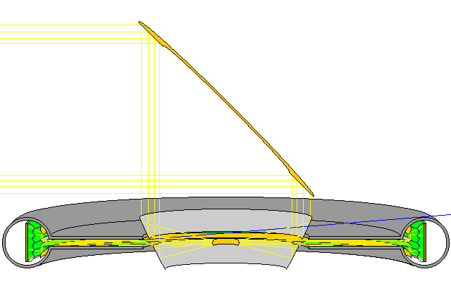
The same principle, of a bottle with a long and narrow neck, can be applied to the Stanford Torus design, producing the modified form of it shown below:

The colony itself is a rotating circular band; it is inside a torus of shielding material with an inner circular slit bordered by two annulus-shaped slabs of shielding. A blue line in the diagram shows how a cosmic ray with the shallowest possible angle of approach still fails to reach the colony. As in the diagram of the previous design, it does strike the shielding close to the colony, and thus, depending on how deeply it penetrates the shielding before being stopped, and producing secondary radiation, there is still a possibility of secondary radiation reaching the colony. In this design, there is no freedom to lengthen the "neck" in the design to reduce this hazard further, but circular walls of shielding material can be added beside the torus of shielding material containing the inhabited cylinder, thus making it wider, to eliminate cosmic rays coming at the most shallow angles.
Note also that in this design, sunlight is reflected five times before it reaches the colonists. The first reflection is from the 45 degree mirror, having an elliptic annular shape, that redirects sunlight to a direction parallel with the rotational axis of the colony. The second is from a mirror formed by rotating a parabola the axis of which is parallel with the rotational axis of the colony, so as to combine bringing the light to the focus of the parabola with another 45 degree change in direction. The third is from a mirror which performs the function of a Cassegrain secondary, turning the focussed light into collimated light. The fourth is from a V-shaped mirror which splits the collimated light into two halves, and the fifth is from a curved mirror designed to distribute the light evenly over the habitat surface. These last two mirrors are shown as being symmetrical in the diagram, but, in fact, because of the design of the second mirror, the upper portion of the disk of collimated light entering the colony will be brighter than the lower portion, and thus the last two mirrors will have to be designed so as to compensate for this.
In the space colony designs in which an impressive vista of space is provided through large clear windows, it has been noted that radiation shielding could be added by the use of "chevron shielding", in which reflecting V-shaped metal troughs are embedded in the glass so that the light travels along a path like that in a pair of periscopes, and radiation is attenuated because any straight-line path to space must go through the metal.

One difficulty with chevron shielding is that there are so many places where glass must be bonded to metal; this would seem to invite the leakage of air, as well as limitations in structural strength. The alternative of embedding the edges of the metal chevrons only in one side of an expanse of glass creates potential stress points from which fractures may start: the vulnerability of glass, once scratched, is well known. Plastic, made from cometary material, might be considered, but in an early space habitat, quartz is a common material, while hydrocarbons, being more difficult to obtain, would likely be used primarily for biomass; while a layer of flexible plastic a fraction of an inch thick might serve for some purposes, a rigid window of plastic several inches thick, providing structural strength under compression as well as tension would seem unrealistic.
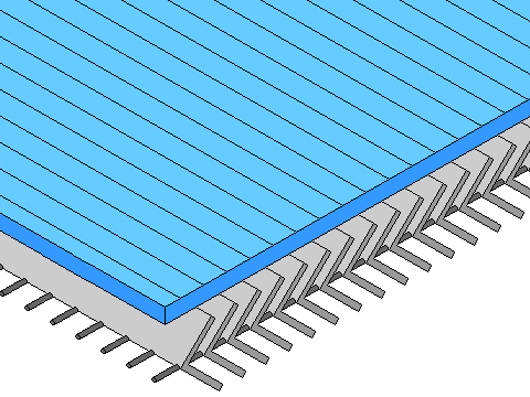
Thus, it seems to me that a more practical design for chevron shielding is something like this:

Metal rods support and space the chevrons, which form a layer separate from a continuous and unbroken glass window. Alternatively, a second layer of chevrons, running in a perpendicular direction, could also be used.