The availability of different floating-point data formats is intended to support the emulation of other architectures by this computer. For this purpose, a bit has also been provided in the program status word labelled leftmost/most significant in high address.
When this bit is set, the leftmost, or most significant, portion of a value occupying several bytes is placed in the memory byte having the highest address. Normally, the opposite is done; the first part of a number is also placed in the first byte occupied by the number.
When the bit is set, the computer is operating in the fashion known as little-endian, while the normal operation of this computer is in the fashion known as big-endian.
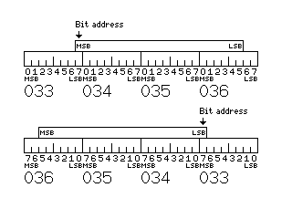
When the bit is zero, the most significant bit of a byte is considered to be bit 0, and the least significant bit is bit 7. When the bit is one, the most significant bit of a byte is considered to be bit 7, and the least significant bit is bit 0. This is relevant for the bit-field instructions in extended operate mode, as they perform bit addressing.
In order to avoid the need to include additional data paths in the hardware to cope with endianness conversions, the implementation of little-endian operation may involve inverting the last several bits of memory addresses under some circumstances.
This is the method used to allow a choice of little-endian or big-endian operation with the PowerPC processors from IBM and Motorola. It was invented, however, by MIPS, which holds a patent for it.
If a computer has a data path which is 64 bits wide, and the intent is that it will always fetch aligned operands with its own native endianness, then, to make it appear to have the opposite endianness, when fetching an aligned 32-bit operand, one bit (the third bit from the last) of the address is inverted, so that the two 32-bit halves of the 64-bit memory entry are reversed. When fetching an aligned 16-bit operand, two bits (the first two bits of the last three) of the address are inverted, so that the four 16-bit quarters of the entry are reversed in order. When fetching a byte, the last three bits of the address are inverted.
It is envisaged that this architecture will be used with a 256-bit data bus, so the bits to be inverted for different types of storage access would be as shown below:
... oooo ooox oooo    128-bit operand
... oooo ooox xooo     64-bit operand
... oooo ooox xxoo     32-bit operand
... oooo ooox xxxo     16-bit operand
... oooo ooox xxxx      8-bit operand

o: not inverted        x: inverted
Given, however, that the design of a large-scale implementation of this architecture is illustrated as using the Level 2 cache to allow operation with alternate word sizes, such as 36-bit words, 48-bit words, or 60-bit words, using the cache to deal with handling little-endian data suggests itself; this would also allow the processor to be used in systems where it, and native little-endian processors, are connected to the same main memory, and use the same addresses to reference its contents.
In this case, the way to proceed would be as follows: the 256 bits of data fetched on the data bus would have the sequence of 8-bit bytes within it reversed, and the memory contents would be placed within a cache line in reverse order.
Externally, when referencing main memory, addresses would be unmodified; internally, when referencing contents of an L2 cache line, addresses would be modified as shown:
... oooo oxxx xxxx oooo    128-bit operand
... oooo oxxx xxxx xooo     64-bit operand
... oooo oxxx xxxx xxoo     32-bit operand
... oooo oxxx xxxx xxxo     16-bit operand
... oooo oxxx xxxx xxxx      8-bit operand

o: not inverted        x: inverted
assuming a cache line of 64 items each 256 bits in length.
Unaligned operands are fetched as if they were composed of multiple aligned values of the largest possible size permitted by their start location. For example, a 64-bit operand starting at an address the last bit of which is a one would be treated as eight 8-bit values, but if the address ended in a single zero bit, it would be treated as consisting of four 16-bit parts, and if the address ended in two zero bits, it would be treated as consisting of two 32-bit parts. This is a general rule, applicable when the computer is operating with its native endianness or with reversed endianness, and regardless of the method used to permit operation with reversed endianness. In the case of an unaligned operand, when operating with reversed endianness, the CPU is responsible for reversing the order of the parts itself either when assembling an operand that has been fetched from memory, or when preparing an operand for storage. Inverting address bits will not eliminate this requirement: the benefit it provides is allowing the elimination of a special data path to change the order of bytes which, forming part of an aligned operand, were fetched in parallel.
The bit marked character data significance direction affects how packed decimal quantities are addressed in conjunction with the preceding bit, as well as the operation of the pack and unpack instructions that convert between packed decimal and 8-bit characters.
Because packed decimal is intended to be closely related to the printed form of characters, it might be thought that it should remain big-endian even when other numeric formats are changed to little-endian form. But this would not be practical when packed decimal arithmetic is handled by a parallel ALU, and when little-endian operation is provided (at least for fully-aligned operands) by inverting some bits of the address. Thus, the handling of packed decimal values is unavoidably somewhat complicated.
When the computer is operating in the mode in which the least significant portion of a multi-byte quantity is in the lower address, it is necessary to apply this to packed decimal quantities as well, in order to permit them to be efficiently loaded into a parallel arithmetic-logic unit. However, packed decimal quantities exist to permit ease of conversion between themselves and the character string expression of the same number. Therefore, when the computer is operating in the mode in which the least significant portion of a multi-byte quantity is in the lower address, the effective address of a packed decimal instruction will be the address of the byte containing the most significant two digits of the packed decimal number, despite the fact that this is the byte of the number which is at the location in memory with the highest address. In this mode, therefore, the P and U instructions have the additional function of reversing the order of the elements of source operand when placing it in the destination operand in converted form. The foregoing only applies when the bit of the Program Status Doubleword governing the Character Data Significance Direction is set to 0. When this bit is set to 1, it is presumed that numbers, when in printed format, appear with their least significant digit in the first position as well, as is the case in documents printed in languages with a right-to-left direction of reading. When the Character Data Significance Direction bit of the Program Status Doubleword is set to 1, then the effective address of a packed decimal quantity is always the address of the byte containing its least significant portion, which will be the byte having the lowest address if the computer is operating in the mode in which the least significant portion of a multi-byte quantity is in the byte with the lowest address, but which will be the byte having the highest address, unlike the case for all other operand types, when the computer is operating in the mode in which the most significant portion of a multi-byte quantity is in the byte with the lowest address. Thus, when the Character Data Significance Direction bit is a one, packed decimal quantities are consistent with other quantities during little-endian operation, rather than big-endian operation, the reverse of the case when this bit is a zero. But in that case, conversion of numbers to printed character decimal form will yield strings which begin with their least significant digit, useful only with languages that are written from right to left, and so that bit will normally be a zero even if little-endian operation is chosen. As noted, the usual mode of operation of this computer is with the Character Data Significance Direction bit set to zero, and with the most significant portion of an operand in the byte of the operand which has the lowest address; in this case, packed decimal operands, like all others, have their effective address referring to the byte within them having the lowest address, and the pack and unpack instructions move in the same direction through both their operands. |
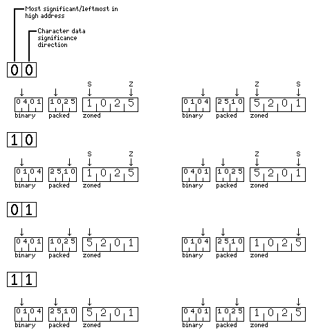
As the foregoing may be difficult to understand, the following diagram, showing the number 1,025, whose hexadecimal representation is 401, in binary, packed decimal, and character formats for all four possible combinations of these modes is shown below:

The left-hand side is drawn in big-endian perspective, with the bytes in lower memory addresses on the left, and the right-hand side of the diagram is drawn in little-endian perspective, with the bytes in higher memory addresses on the left. Since character strings are always stored with their first character in the lowest memory address, however, the big-endian side of the diagram reflects the printed appearance of character string data, unless a language which is printed from right to left is used.
The arrow above each quantity shows the byte whose address is also that of the whole number; in the case of zoned decimal values, there may be two arrows, one labelled S, indicating the address of the number considered as a character string for string instructions, and one labelled Z, indicating the address of the number for zoned decimal arithmetic instructions.
Within a byte, on both sides of the diagram, the bits which are most significant are on the left, and, therefore, in a packed decimal quantity, of the two decimal digits within the byte, the most significant digit is on the left. Thus, the diagram that shows a little-endian perspective places the bytes in higher memory addresses on the left, which makes the little-endian mode of operation the one in which a number consistently begins with the most significant digit on the left, continuing to the least significant digit on the right. The direction in which individual bits are numbered is reversed in little-endian operation to match the orientation of byte addresses, as this diagram, used to illustrate how bit field operations are affected by the two different types of endianness, shows:

Since whether data items are represented in little-endian or big-endian format forms part of the numeric format, and it is possible for two numeric formats to be in use at one time, whether instructions are in little-endian or big-endian form must be specified by a separate bit of the Program Status Block.
Instructions are considered to consist of consecutive 16-bit values, or consecutive values of another length in a variant alignment mode. Because instructions are coded so as to have the prefix property, and occupy distinct portions of opcode space, it would not be possible to allow the ordering of these values to be completely reversed, from beginning to end, by this bit, but the order of the two bytes within each 16-bit value, or, in the case of a variant alignment mode with 32-bit alignment, the four bytes within each 32-bit value, to be affected. Since it is possible, even if uncommon, for unaligned 32-bit values to form part of an instruction with 16-bit alignment, this would mean that reversing byte order in instructions would not lead to them being composed consistently of little-endian elements.
This can be taken care of consistently, while placing the prefix property of instructions in no jeopardy, by also reversing the two 16-bit elements of either a 32-bit value in an instruction, or two 16-bit elements which contain a numeric field that crosses a 16-bit boundary, for example, in short page mode when the address field is increased in size from 12 bits to 28 bits.
Note also that no part of the status of an individual process can be permitted to change the location or format of interrupt vectors in any way. Just as a bit in the control registers is used to shift the interrupt vectors from the end of memory, where a read-only-memory used during initial startup may be present, to the beginning of memory, it would also be possible for a global status bit in the control registers to make the interrupt vectors little-endian, however, to permit the processor to be used within a consistently little-endian setting.
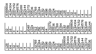
If little-endian operation were permitted in combination with changing the word and character size of the computer, the diagram below illustrates the consequences:

If the mapping of bits to memory is defined, as implied by the layout of the diagram, on the basis that characters with lower addresses are treated as being located to the left of characters with higher addresses, then changing from one character width to another will, in little-endian mode, and in little-endian mode only, change the place value of some of the bits in a number.
Of course, it is equally possible to treat characters with lower addresses as being located to the right of characters with higher addresses, in which case this phenomenon will only be exhibited in big-endian mode.
Also, it is possible to achieve consistent operation, in which changing the character width would not affect the place value of any bit in either mode; this, however, would require the switch to little-endian operation to reverse not merely the place value of characters within a word, but also the place value of bits within a character.
Although in existing architectures in which a switch between big-endian and little-endian operation is offered, the change normally does not affect how characters are stored, since the switch can be implemented by modifying memory addresses, and, if this is done, the apparent order of characters in character strings is changed by a switch between modes, it should be clear that alternating between these modes is normally intended as something done infrequently; perhaps only by the operating system and not by applications, but even more commonly something done exactly once, when a specific hardware platform employing a given processor chip is specified.
In addition, if the switch between big-endian and little-endian operation is obtained by modifying memory addresses, then consistent operation is also obtained, but without any bit reversal, since in that case, the most significant and least significant bits of a word remain fixed, and only the location of the fields within a word representing successive characters is changed, from starting at the most significant end in the big-endian mode to starting at the least significant end in the little-endian mode.
To permit consistent handling of unaligned operands as well, little-endian mode may be implemented, despite the absence of data types wider than 128 bits, by reversing the location of bit fields of whatever width within the entire span of the 256 bit data bus to memory envisaged as characteristic of a possible implementation, or even within the entire span of a 4,096-bit cache line. Since filling the internal portions in a cache line in reverse order involves no inefficiency, it is possible to do both at the same time. This would be the most efficient and practical means of implementing both big-endian and little-endian operation in the context of the general design described at the beginning of this chapter.
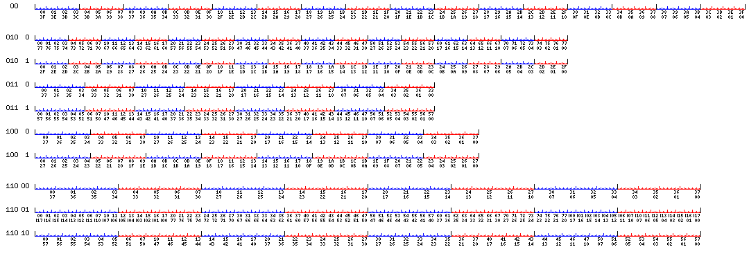
The following diagram may help to make how this would work more comprehensible:

The 512-bit width of this diagram is to be thought of as representing a scaled-down version of the 4,096-bit cache line envisaged for this architecture. The memory bus would be 32 bits wide, scaled down from 256 by the same factor of eight, and so a cache line would be filled by means of either sixteen, twelve, nine, ten, or fifteen memory accesses, so that successive words in memory would be contiguous, and main memory would be used at full efficiency, regardless of which width was used for data words.
None the less, in consequence of the foregoing, for this architecture little-endian operation need only be supported, and its results need only be defined, when the computer is operating with its default word length of 32 bits. This is not a serious limitation, as little-endian operation, historically, had only been used with computers having the eight-bit byte size and data format widths which were powers of two. It is envisaged that only those implementations which can offer full support for little-endian operation for alternate data widths with little or no additional circuitry will offer this feature, to be considered model-dependent.
Some computers that place the most significant portion of values that occupy more than one location in the storage location with the lower-numbered address, and thus are known as big-endian, are the IBM 360 and the Motorola 6800 and 68000, and their successors.
Some computers that place the most significant portion of values in the later location, and thus are known as little-endian, are the PDP-11, the Intel 8080 and 8086, the MOS Technology 6502, and the National Semiconductor 16032 and their successors.
Many classic computers, the Honeywell 316 being one example, operated in a hybridized big-endian and little-endian fashion. When multiple characters were placed in a single word of storage, the first character was placed in the portion of the word corresponding to the most significant part of the word. When the computer performed calculations on longer numbers that occupied more than one word, however, the word in the lower memory address was the less significant word. This was a consequence of initially assigning characters to portions of a word in the way that seemed natural, the big-endian way, and then implementing multi-word arithmetic in the most efficient way by fetching the least significant portion of the operand first, so that carries from it would be available in the next memory cycle. While a small amount of extra circuitry would have allowed big-endian multi-word quantities to be added with equal speed by fetching the second word first, extra circuitry was at a premium in early minicomputers, even if it was not a problem for a mainframe like the IBM 360, which included the capacity for packed decimal arithmetic to handle commercial data processing.
This is what led to the concept of consistent little-endian operation being conceived by the designers of the PDP-11 minicomputer, since this made the relationship between numbers and characters uniform and consistent while still retaining the efficiency and low gate count of little-endian multi-word arithmetic.
My personal opinion on this matter is that, despite the justifiable reasons for the popularity of the PDP-11 computer, which led to a generation of programmers in certain areas of the industry being introduced to computing by means of it, and despite the elegance of consistent little-endian operation as a solution to the issues faced by its designers, and even despite the trend towards exclusive reliance on compiled languages, making the ease of comprehension of a computer's internal workings less of an issue, given the gate counts of modern microprocessor chips, there is little excuse for perpetuating the confusion that is the inevitable result of the continued use of little-endian data representation.
But that's just a personal opinion. The argument that little-endian versus big-endian is just a convention, with little-endian being more "natural" to people whose native languages are Hebrew and Arabic, so that the computing world should settle on little-endian universally given that it has the real advantage of making multi-precision arithmetic simpler on smaller processors, still used at least in embedded applications, and the real conceptual advantage that the place value of the first byte, and every succeeding byte, in a number is strictly determined independently of its length, is not without validity as well.
In the case of the IBM System/360, however, big-endian made sense, and was indeed the only possible choice. That's because the 360 didn't just perform binary arithmetic. It also performed arithmetic on packed decimal numbers.
Instructions to convert from character strings to packed decimal form were provided. Obviously, these instructions were simpler because the four-bit digits inside a packed decimal number were in the same order as the eight-bit digits in the character string representing the same number.
If one were going to take a packed decimal number, and move it, eight digits at a time, into the same 32-bit ALU (or 16-bit ALU, or 8-bit ALU, depending on the model of the System/360 under consideration) that was used for doing arithmetic on binary numbers, adding some extra circuits to detect nibble carries and perform decimal adjustment, then that operation would be simplified if binary numbers were also, like packed decimal numbers, ordered with their most significant part first.
In many computers, character strings and binary integers belong almost to two separate worlds, so that little-endian byte order means that binary integers are not ordered the same way as the character string representation of a decimal number is not important, except to beginning students of assembler programming who might be confused a little at first. But when a computer includes packed decimal arithmetic in order to avoid the overhead of decimal to binary conversion because it is oriented to database or commercial computation, then there is a bridge between character strings for numbers and numbers in binary arithmetic format that makes having them go in opposite directions a problem.