Instructions longer than 32 bits, like 17-bit instructions, may only be present in
blocks that either begin with the four bits 1111, which is followed by a
sequence of fourteen pairs of bits, each of which constitutes a prefix
field, associated with each of the 16-bit halves of the remaining 32-bit instruction slots in the block,
or which begin with a closely related header type, specivically, the header types
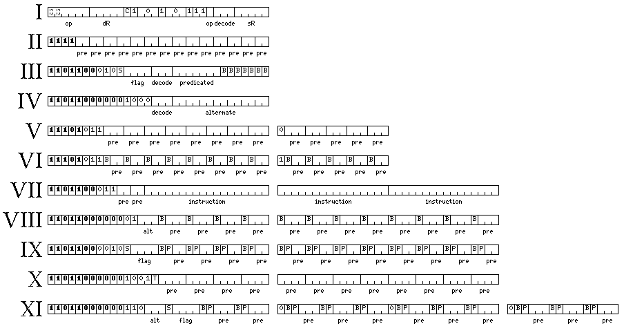
shown as V, VI, VIII, IX, X, and XI in the diagram below, or in blocks of other types if they
are encapsulated within an instruction bundle in the manner explained in the first page of this section.
This header format is illustrated as the format of type II in the diagram below, which also appeared on the first page of this description of the Concertina II architecture:

Note that in the 32-bit instruction slot the contents of which begin with 1111 appearing
in the diagram above, the rightmost prefix field always corresponds to the last 16 bits
of the 256-bit block, and so as many of the leftmost prefix fields are unused as there
are header instruction slots preceding that instruction slot.
When variable-length code is in use, the contents of the prefix field have the following values:
0 followed by another bit, which signifies that the second bit of the prefix
field is the first bit of a 17-bit instruction, the remaining bits of which are in the corresponding 16 bits
of the block;
10, which signifies that the corresponding 16 bits in the block are the first 16 bits of
an instruction; and
11, which indicates that the corresponding 16 bits in the block do not begin an instruction,
and may be later bits in an instruction, or space used for a pseudo-immediate value, or space that is either
unused or used for some other purpose.
Normally, when the prefix bits are 10, then the corresponding 16 bits in
the block will be the first half of a 32-bit instruction, but they may also be the first 16 bits of an
instruction longer than 32 bits.
In this case, the first four bits of the instruction will be 1111, as this bit pattern is
unused in 32-bit instructions, having been reserved to indicate the instruction slot with prefix
bits, for which purpose it is no longer needed.
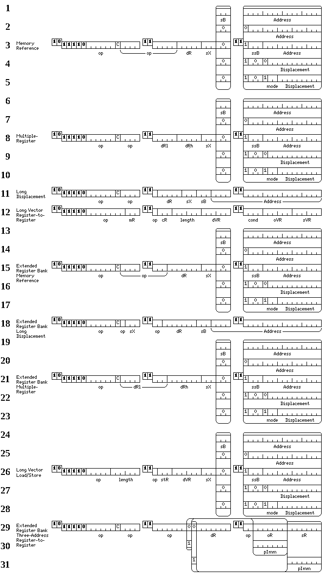
The formats of 48-bit instructions are shown below: in these instructions, the leading 1111
is followed by 0 to indicate that the instruction is 48 bits long.

Note that among the memory reference instructions shown in lines 1 through 5, there are memory-to-register operate instructions, which is why a C bit is present, some of which are included in the 32-bit instruction set as supplemental memory-reference instructions of the second kind, and there are memory-to-registers acting on types of data other than the most basic types, some of the load and store instructions among which are included in the 32-bit instruction set as supplemental memory-reference instructions of the first kind.
The formats of 64-bit instructions are shown below: in these instructions, the leading 1111
is followed by 10 to indicate that the instruction is 64 bits long.

In these diagrams, the prefix bits associated with each 16 bits of the instruction are shown raised on the left, followed by the 16 bits of the instruction to which they correspond.
The reason that one bit of the instruction is interposed before the sequence of bits that indicates the length of the instruction is apparent from the diagrams: since that sequence of bits varies in length, having a bit of the instruction precede the sequence allows that bit to be used as the C bit for operate instructions, which indicates whether the instruction is allowed to set the condition codes, and that allows that bit to have the same position for all instructions of this type.
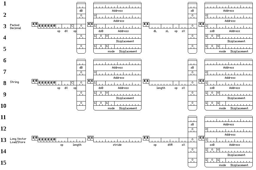
The 80-bit un-indexed three-operand string translate instruction is shown below:

and then the fully-indexed 96-bit translate instruction:
