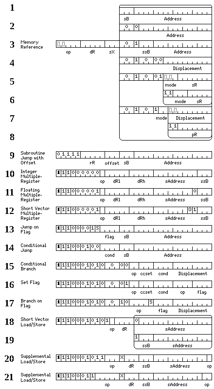
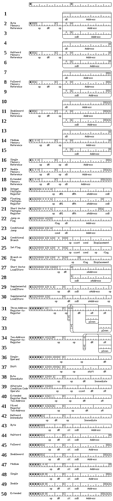
The formats of the basic 32-bit instructions for this architecture are shown in the two diagrams below:
First, the instructions that are 32 bits in length which can never affect the condition code bits, as they perform functions such as load and store, or jump, are shown.
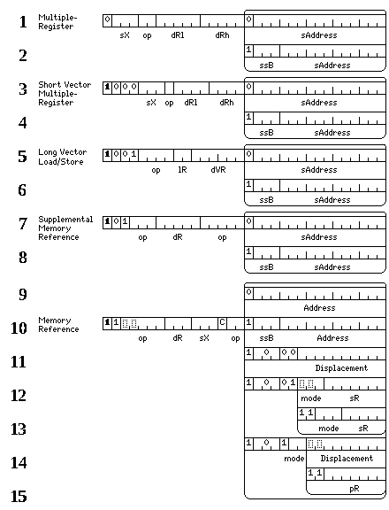
The 32-bit form of basic load and store instructions is shown in lines 1 through 8.
For a memory-reference instruction, the five-bit destination register field specifies one of 32 registers, either the general-purpose registers for integer instructions, or the floating-point registers for floating-point instructions.
The index register field contains a number from 0 to 7, if it contains 0, the instruction is not indexed; if it contains any other value, that value indicates which general register is to be used as the index register for that instruction.
Lines 1 through 8 show the eight possible formats for 32-bit memory-reference instructions.
In line 1, a three-bit field indicates the base register. It may contain any value from 1 to 7, which indicates that a general register from 25 to 31 respectively is used as the base register.
Line 2 of the original diagram shows the second possibility: a 15-bit displacement is included in the instruction, and general register 16 contains the starting point of the 32,768-byte area of memory to which the values of this displacement may refer.
Line 3 of the original diagram shows the third possibility. Here, the displacement is 12 bits long, and there is a three-bit ssB field (short source base) adjacent to it.
If that field contains a number from 1 to 7, it indicates that a register from 17 to 23, respectively, is used as a base register, the contents of which point to a 4,096-byte area in memory.
If that field contains a 0, then one of the possibilities shown in lines 4 and 5 of the diagram apply.
Line 4 of the original diagram shows this possibility: if the ssB field, containing a 0, is followed by 00, then program-relative addressing is indicated.
The instruction now contains an 10-bit displacement, which is in units of bytes, but now it is a signed two's complement value from -512 to 511, relative to the position immediately after the end of the instruction. One particularly important application of this addressing mode is at the beginning of a main program or a subroutine, where a Jump to Subroutine instruction having the following instruction as its destination can be used to initialize a base register by means of which adresses referring to the program code can be constructed.
Lines 5 and 6 of the diagram are chiefly concerned with the register indirect addressing modes.
In line 5, we see where the ssB field, containing zero, is followed by 01, and the following mode field contains a value from 0 to 5, indicating an addressing mode used with one of the registers in the extended register bank.
These modes are:
000 Register Indirect

010 Register Indirect with Scaled Auto-Increment
011 Register Indirect with Scaled Auto-Decrement
In line 6, the ssB field again contains zero, and is followed by 0111 and then
a mode field. This field applies either to a register from the normal bank of
32 integer registers, or, in one case, the field normally specifying a register instead
contains a pseudo-immediate pointer. The modes are:
000 Register Indirect

010 Register Indirect with Scaled Auto-Increment
011 Register Indirect with Scaled Auto-Decrement

111 Absolute
In the absolute addressing mode, which may be indexed, the source register field instead contains a five-bit pseudo-immediate pointer which points to a 64-bit pseudo-immediate used as the address of the instruction.
For all load operations, auto-increment and auto-decrement are performed after the load operation; for all store operations, auto-increment and auto-decrement are performed before the store operation. In this way, it is possible for stacks to grow either up or down in memory, whereas, if whether an auto-increment or auto-decrement were performed had determined the ordering of operations, a specific direction of stack growth would be imposed.
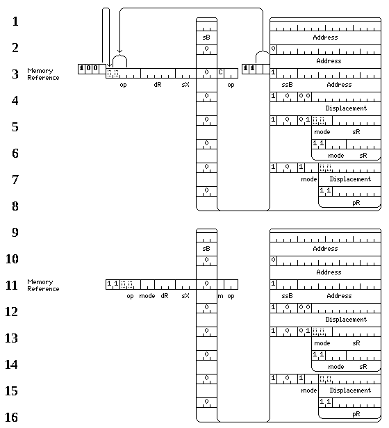
Lines 7 and 8 of the diagram show the formats for two other addressing modes.
If the ssB field,
containing a 0, is followed by 100, then it indicates Array Mode addressing.
Here, the contents of register 16 are added to the displacement, which is now in units of 64 bits or eight bytes, to indicate the location of a 64-bit pointer to an array.
|
Unless the displacement begins with
|
If indexing is present in the instruction, the contents of the selected register are added to that pointer in order to address an element of that array. Thus, Array Mode provides post-indexed indirect addressing in order to conveniently allow a program to refer to up to 512 arrays which are larger than 65,536 bytes in size without having to reload base registers in order to access them.
If the ssB field,
containing a 0, is followed by 101, then Address Table addressing is indicated.
Here, the contents of register 16 are added to the displacement, which is now in units of 64 bits or eight bytes, to indicate the location of a 64-bit constant containing the effective address of the instruction.
If indexing is present in the instruction, the contents of the selected register are added to the initial effective address formed by adding the contents of register 17 to the displacement, so as to change which 64-bit constant is taken as the effective address.
Thus, Array Mode addressing provides pre-indexed indirection, and Address Table addressing provides post-indexed indirection. Array Mode addressing is useful for accesing data in multiple large arrays without reloading base registers, and Address Table addressing is useful for such things as multi-way jump tables.
If the ssB field, containing a 0, is followed by 110, then Array Mode with
Auto-Increment addressing is indicated. The displacement is in units of 64 bits, and
the contents of integer register 16 are added
to the displacement after scaling to find the address to be used; this address may be indexed to form
the effective address, and, in addition, after the memory location at the effective address so calculated
is accessed, the index register is then incremented by the size of the operands of the instruction;
incremented by one if the instruction acts on bytes, having eight added to it if the instruction acts
on double-precision floating-point numbers, and so on. This includes adding six in the case of medium
floating-point numbers.
If the ssB field, containing a 0, is followed by 111, then Array Mode with
Flexible Auto-Increment
addressing is indicated. Here, if the instruction is indexed, the index register must be one of
registers 2, 4, or 6, and the amount by which it is incremented after memory access is found in the
following register.
The subroutine jump with offset instruction makes use of the opcode which would indicate an "unsigned load long" instruction; since the long data type is as long as a complete integer register, such an operation is not needed; similarly, the opcode for "insert long" is used for Load Address instead.
The format of the subroutine jump with offset instruction, which places the offset added to the value placed in the return register after a shift left in the field which would normally specify an index register, is shown in line 9.
Lines 10, 11 and 12 of the diagram show the formats of the multiple-register load and store instructions:
1400xx xxxxx LM    Load Multiple
1401xx xxxxx STM   Store Multiple
1402xx xxx0x LMF   Load Multiple Floating
1403xx xxx0x STMF  Store Multiple Floating
1402xx xxx1x LMSV  Load Multiple Short Vector
1403xx xxx1x STMSV Store Multiple Short Vector
Note that these instructions, in particular the ones for the floating-point registers, load and store their contents in raw internal form. Because of the complexities of the IEEE 754 format for floating-point numbers, they are converted to an internal form when loaded into the floating-point registers, and converted back to the standard form when stored from those registers, to allow register-to-register arithmetic to proceed more quickly.
As these instructions, with both a low and high register specified, require a considerable amount of opcode space, they have been restricted to aligned operands.
Lines 20 and 21 show the form of the Supplemental Load and Store operations. These instructions perform load and store operations from memory for operands of additional specialized types which are supported by some of the operate instructions with longer opcodes.
In order to allow these instructions to fit in the available opcode space, they have a number of limitations. These are the ones that apply to the format in Line 21:
Actually, there may be an issue with that last limitation, because the types normally dealt with by this category of instruction may include types that are 48 bits long, which only have natural 16-bit alignment. The instruction format in line 20, with a smaller opcode field, addresses this limited number of cases,
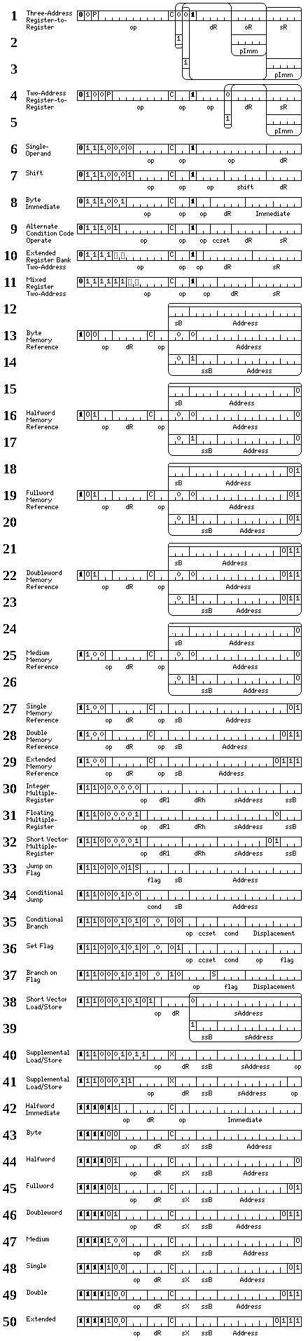
The diagram below shows the format for 32-bit instructions which perform arithmetic operations, and which may affect the condition codes:
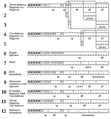
A three-address register-to-register operate instruction is shown in lines 1 through 3; either one of the source and operand registers may be replaced with pointers to pseudo-immediate operands. As the result of the instruction would be a constant if both of those operands were so replaced, this combination is illegal, and the bit pattern it would have is reserved for future expansion of the instruction set.
Two-address register-to-register operate instructions are shown in lines 4 and 5. These have a considerably larger space available for the opcode field, and, thus, are not restricted to the basic arithmetic operations provided for three operands. The bit marked P in the instruction indicates that pseudo-immediate operands, if called for by the instruction, are to be fetched from a buffer storing the contents of the previous instruction block executed rather than the current block, unless it is instead indicated by the current block header that another buffer, into which the contents of a block are stored only when explicitly indicated by the header (such indication resulting from the H bit being set in headers of types), is to be used instead. This happens in the case where the I bit is set in headers of types
Line 9 shows a two-operand register-to-register operate instruction that can use any of eight possible sets of condition codes, if the C bit is set, instead of just the normal set of condition codes. Like the flag bits used with instruction predicatiion, alternate sets of condition codes are a way to allow conditional branches to be delayed so as to reduce the need for branch prediction.
Lines 10 and 11 show register-to-register operate instructions that involve extended register banks, both integer and floating, with 128 registers instead of 32 registers. Larger register banks permit more operations to be performed before there is a need to re-use a register from which the result has been stored, reducing the occurence of hazards in pipelined code.
The mixed register two-address instructions in line 13 allow the large register banks to interact with the normal register banks.
The format of the subroutine jump with offset instruction is shown in line 17; this instruction begins with the same bits as the Type XVII header, and thus may not appear in the first instruction slot of a block without a header, or the instruction slot following a prefix header.
The contents of the offset field, shifted one place to the left, are added to the address of the location immediately following the subroutine jump instruction to form the return address.
This allows more efficient and rapid processing of returns from subroutines when the subroutine jump instruction precedes space reserved for pseudo-immeidates and/or a block header, which stand between it and the next instruction to be executed.
It is for this reason that the initial bits of the Type XVII header may be used as the opcode of this instruction, as it is only needed as the last instruction in a block (although if pseudo-immediates are present, it need not necessarily be in the last instruction slot in a block).
A second group of operate instructions are shown in the diagram below:
These are memory to register operate instructions. In order to fit them in to the available opcode space, multiple restrictions have had to have been imposed on this group of instructions:
Even with these restrictions, it should be possible to make use of the ability to combine a fetch of data from memory with an operation to save instructions.
The header formats of type X and XIII provide for an alternate 32-bit instruction set, and a set of 33-bit instructions.
The 33-bit instructions have this form:
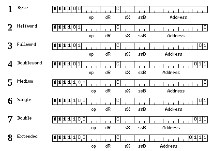
Lines 1 through 5 show memory-reference instructions in which the opcode field is increased from five bits to seven bits in length, so as to allow memory-to-register operate instructions. To compensate for this, the destination register field is reduced from five bits to three bits in length, which means that only registers 0 through 7 can interact wih memory in this fashion.
But since these are operate instructions, a condition code bit is in order, which is why these instructions have been classed as 33-bit instructions.
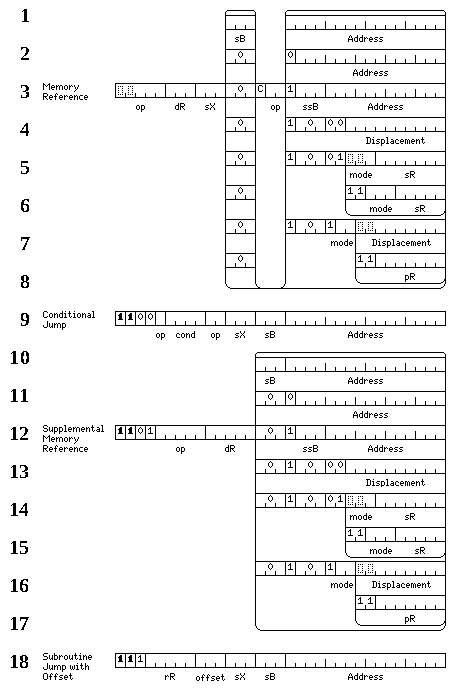
In addition, an indexed version of both the conditional jump instructions and the subroutine jump with offset instruction have been included in this group of alternate instructions.
As well, lines 7 through 11 of this diagram show the supplemental memory-reference instructions; these allow load and store operations for additional data types for which operate instructions, but not memory-reference instructions, are available in the basic instruction set.
The alternate 32-bit instructions have this form:
providing an indexed version of the multiple-register instructions, long vector load/store and supplemental memory reference instructions with longer opcodes, and memory-to-register operate instructions, which, however, cannot use 16-bit displacements, and which may only have the first eight registers as their destinations.
The header format of type V, when the option bits in it are
set to 00, also provides for 35-bit instructions. These
instructions have the form:
allowing for memory-reference operate instructions that can have all 32 registers as their destinations.
Also provided for are load-store operations, with only the first eight registers as their destinations, which combine addressing modes even with 16-bit displacements. Three bits indicate the addressing mode; the two-bit mode field, and the bit marked m in the position of the condition code bit for the operate instructions.
The addressing modes are:
000 conventional addressing

010 scaled auto-increment of byte index
011 scaled auto-decrement of byte index
100 scaled index

110 auto-increment of scaled index
111 auto-decrement of scaled index
Scaling is only by a shift, and so does not work with the Medium floating-point type.
Also, in Augmented Short Instruction Mode, the basic memory-reference instructionms are modified to make additional opcode space available; other 32-bit instructions are re-organized as well; the other memory-reference instructions are simply moved by having one bit changed, while the operate instructions gain longer opcode fields. The instruction set in this mode, except for the 15-bit instructions which replace the 14-bit instructions, shown on a later page, have the form:
In this mode, memory-reference instructions include operate instructions as well as load/store instructions; only 16-bit displacements with their associated base registers are available; and all operands must be fully aligned according to the size of their type.
Note that because the opcode fields are longer, in this instruction format, the three-address operate instructions also include a P bit, to allow the use of pseudo-immediate values from within a previous block.
Also, an additional set of extra instructions are provided in this instruction format:
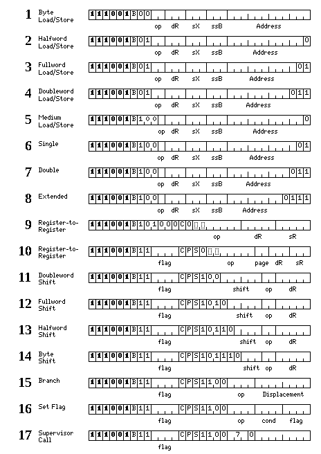
These instructions include a shortened version of the load and store memory-reference instructions, as well as the operate instruction from 17-bit short instructions, which all include a break bit, and, in addition, the instructions from the 15-bit short instruction format which also have added to them a predicated bit, a sense bit, and a flag field, so that the VLIW features can be used even when a simple header merely invokes instructions of the Augmented Short Instruction format, rather than a header explicitly oriented towards the use of those features. Of course, in the latter case, a more complete set of instructions can be used with those features.
In the case of a Type IX header, an X bit is available which can be used to call for an alternative version of this mode:
Here, the operate instructions are left as they are in the basic instruction set, without any increase in the size of their opcode fields, in order that a break bit can be provided for the second 15-bit instruction in a pair as well as the first.
The set of extra instructions noted above is also available in this modified version of the format, as it uses leading bits normally used for a header, which aren't used for that purpose after a header.