Instructions longer than 32 bits may be present in blocks with a header in the Type I format.
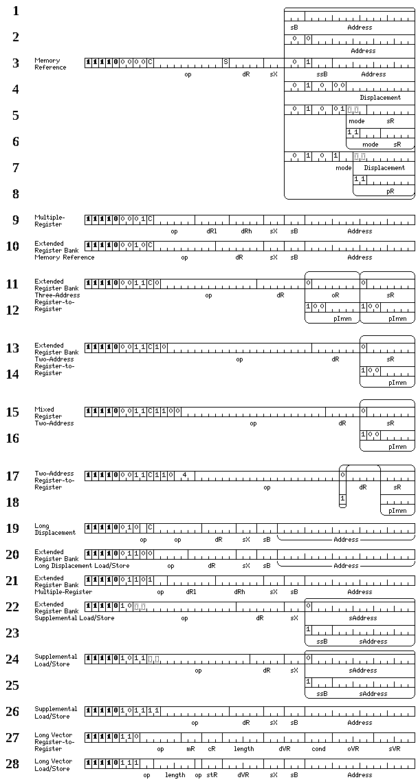
The formats of 48-bit instructions are shown below. First, the primary series of these
instructions, which all begin with 11110:
Note that among the memory reference instructions shown in lines 1 through 8, there are memory-to-register operate instructions acting on types of data other than the most basic types, some of the load and store instructions among which are included in the 32-bit instruction set as supplemental memory-reference instructions.
Also note the presence of a bit marked as S. This bit is used to indicate scaled indexing; if the instruction is indexed, and the type of operand of the instruction is other than byte, the value in the index register is shifted left before use by as many places as appropriate so that the index is in units of the operand length; one place for halfwords, two places for integer and floating values, three places for long and double values, and four places for quad values. In the case of Medium floating-point operands, a shift of one place to the left is applied in accordance with their alignment, as opposed to attempting to multiply by six during address calculation.
Line 9 shows multiple register instructions. These have a C bit, because operate instructions involving multiple registers with a vector in memory are possible here.
Line 10 provides memory-reference instructions, including memory-reference operate instructions, for the extended register banks of 128 registers.
Lines 11 and 12 illustrate three-address register-to-register operate instructions for the extended register banks of 128 registers.
Lines 13 and 14 illustrate two-address register-to-register operate instructions for the extended register banks of 128 registers.
Lines 15 and 16 illustrate two-address register-to-register operate instructions with a register from the regular 32-register banks as the destination, and a register from the extended register banks of 128 registers as the source.
Lines 17 and 18 illustrate two-address register-to-register operate instructions, using the regular 32-register register banks.
Line 19 provides memory-reference with 20-bit displacements for registers within the regular sets of 32 registers.
Line 20 allows load/store memory-reference instructions with a register in the extended register banks of 128 registers as the destination, and the source memory operand being indicated by a 20-bit displacement, with a base register among integer registers 9 through 15.
Line 21 shows the multiple register instructions for the extended register banks. These are only the basic operations of load, store, load floating and store floating. There are no extended register banks for short vectors, so corresponding instructions for that are not required.
Lines 22 and 23 show the format of supplemental load/store operations with a longer opcode, to allow additional data types to be used, for the extended register banks of 128 registers. In order to provide this, only 15-bit and 12-bit displacements are used.
Lines 24 and 25 show the format of supplemental load/store operations with a longer opcode, to allow additional data types to be used, for the normal register banks of 32 registers. In order to provide this, only 15-bit and 12-bit displacements are used.
Line 26 shows the format of supplemental load/store operations, so that load and store operations can be performed for the many data types for which operate instructions are provided.
Lines 27 and 28 show the formats of instructions which operate on long vectors.
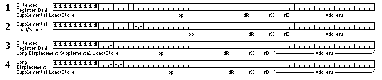
Then, the diagram below shows the formats of instructions belonging to a second series of
48-bit instructions, each of which begins with 111111110:

As well, as there is some available opcode space within the 17-bit short instructions, some
additional 48-bit instructions may be indicated within a Type I header; the first 16 bits of
the instruction are indicated with the prefix code 01, indicating a 17-bit short
instruction beginning with a 1, instead of the usual prefix code 10
used to indicate instructions which are 32 bits long or longer. This diagram shows the form
of these instructions:
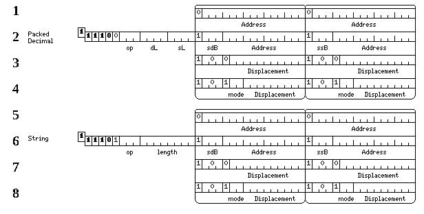
The 1 bit in the raised box represents the one from the prefix code, which is
additional to the 48 bits of the instruction proper.
As these instructions are not distinguished, by their first few bits, from the ordinary 32-bit instructions, the special technique that allows instructions longer than 32 bits to appear within blocks that begin with a Type II or Type III header is not available for these instructions.
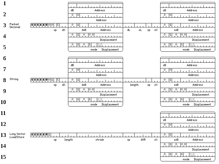
The formats of 64-bit instructions are shown below. First, the primary series of these instructions,
all of which begin with 111110.
And then the secondary series of these instructions, which all begin with 111111111:
The formats of 80-bit instructions are shown below: these instructions
begin with 1111110. So far, only the un-indexed three-operand string translate
instruction is defined for this length:
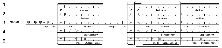
The formats of 96-bit instructions are shown below: these instructions
begin with 11111110. So far, only the fully-indexed 96-bit translate instruction
is defined for this length:
