A fundamental unit of 12 bits allows items of 36 bits, 48 bits, and 60 bits in length to be addressed. But a 12-bit wide data bus is needlessly slow, and attempting to confine most instructions to a 12-bit word is also limiting.
Back when the speed of computer memories was comparable to that of the arithmetic unit in the CPU itself, so that computers tended to have a single accumulator rather than several general registers, a 24-bit instruction word had enough room for a six-bit opcode, a fifteen-bit address (reaching 32,768 words of memory), and three extra bits for addressing modes.
Is it possible to bring the 24-bit word into the modern era of computing?

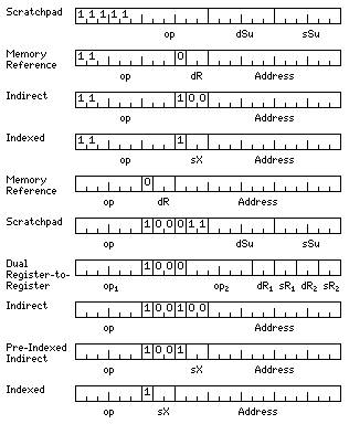
The illustration above shows an example of an instruction word format intended to address these goals.
Instead of 64 possible 6-bit opcodes, in the diagram the possible instructions are divided into 48 with 6-bit opcodes, with the formats in the last six lines of the diagram, and 112 with 9-bit opcodes, with the formats in the first four lines of the diagram.
Instead of having one bit to specify indirection, and two to specify an index register, as in many classic 24-bit computers, one bit indicates if the next two specify one of four general registers as the destination of the operand, or an index register; in the latter case, register 0 is the destination.
Since 100 would be a duplicate of 000, destination register 0 without indexing, given the convention that specifying index register 0 means no indexing, it is used instead to indicate additional addressing modes.
Given four general registers, it is possible to fit two register-to-register instructions in a single 24-bit word, and that is perhaps the most important additional mode to add.
Using an address field of only 12 bits, so that the destination has to be more local, indirect addressing can be added. Plain indirect addressing is indicated by zero in the index register fiels. Pre-indexed indirect addressing is selected by a bit that is unused when putting two register-to-register instructions in a word.
RISC-like instructions can be squeezed in because of the limitation on the range of the 6-bit opcodes. The four general registers are the first of the 64 registers, to allow data to go in and out of those registers without adding additional instructions.
In the case of the instructions with 9-bit opcodes, since both indirect addressing and RISC-like instructions are highly desirable, but there is only room for one of them made by index register zero, so room is made for the other mode by reducing the number of 9-bit opcode instructions by 16, from 128 to 112.
Address constants could be 48 bits long, beginning with an index bit and followed by two bits which, if nonzero, indicate indexing and specify the index register used. A 45-bit address is comparable to the address buses actually used with many devices using 64-bit addressing.
Dividing memory into 32K and 4K pages avoids the need to perform an addition when generating addresses if indexing is not used, although this is a technique generally abandoned after the early era of computers. It does have the desired modern effect of encouraging locality of reference.
The 48 instructions with six-bit opcodes could include 16 instructions for each of two integer types and 8 instructions for each of two floating-point types. If the integer types are 24 bits and 48 bits long, and the floating-point types are 48-bit intermediate and 96-bit extended, the 15-bit address fields might as well be displacements in units of 24-bit words.
Among the 112 instructions with 9-bit opcodes would be the integer instructions operating on 12-bit halfwords and the floating-point instructions operating on 36-bit single precision numbers and 60-bit double precision numbers, so the 12-bit address fields would be displacements in units of 12 bits. Thus, index register contents and address constants would also be in units of 12 bits, these being the basis of addressing.
Indirect addressing, although a holdover from an earlier era, allows instructions to, in effect, be longer than 24 bits without having to complicate instruction decoding by having instructions of different lengths. And this also helps to make it possible to cope with the division of memory into pages of 32K or 2K words.
Given the limitation to 112 instructions with 9-bit opcodes, words with the first eight bits all ones won't be used for the scratchpad format, so these can be used for instructions that operate on the contents of a single general register, such as shift, absolute value, and negate, following the same principle as the operate instructions with opcode 7 on the PDP-8.
Another approach is illustrated in the diagram below:

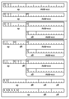
The image is divided into four boxes, each representing a mode of operation.
The first box shows the format of memory-reference instructions on some historic 24-bit computers that were limited to memories of up to 32,768 words in length. Here, though, individual 12-bit storage units would be addressable, so the maximum memory would only be half as large; this accomodates the target floating-point types which occupy an odd number of storage units, 36-bit single precision and 60-bit double precision.
The second box shows an alternate mode to allow access to a larger memory. The memory would be divided into pages of 16,384 12-bit storage units, or 8,192 words, and the P bit, if zero, indicates the instruction refers to the first page in memory, and if one, indicates the instruction refers to the page containing the instruction itself.
This allows the memory to be larger than 32 K storage units; in this mode, it is envisaged that address constants referenced by indirect addressing (indicated by the first bit of the instruction) would also start with an I bit and two index register bits, like instructions, and so the remaining 21 bits would be available to allow reference to 2,097,152 storage units, or 1,048,576 (24-bit) words of memory.
The third box shows an attempt to provide this legacy 24-bit architecure with an even more sophisticated way of addressing memory. Now there are nine base registers, one indicating the start of an area of 16,384 storage units, and the other eight indicating the start of areas each with 2,048 storage units.
To allow this increased sophistication to come with the ability to address a larger memory, multi-level indirect addressing would be dropped; a plain 24-bit address, accessed through indirect addressing, or through placing suitable values in the 24-bit long base registers, means that now 16,777,216 storage units, or 8,388,608 words of memory are accessible.
The fourth box illustrates how one can then proceed to abandon the legacy 24-bit architecture, and move to a contemporary RISC architecture, despite having a 24-bit word instead of a 32-bit word for instructions.
Only 12 opcodes are available for memory-reference instructions in this mode, and there are only three index registers, limitations that seemed the best way of coping with the short instruction word.
The format for memory addresses is the same as in the preceding mode, but now there are 32 integer registers which are 48 bits long, and the base and index registers are assigned to them, allowing a much larger memory.
The available memory-reference instructions will be:
00xxxxxx LH  Load Halfword
04xxxxxx STH Store Halfword
10xxxxxx L   Load
14xxxxxx ST  Store
20xxxxxx LL  Load Long
24xxxxxx STL Store Long
30xxxxxx LF  Load Floating
34xxxxxx STF Store Floating
40xxxxxx LD  Load Double
44xxxxxx STD Store Double
50xxxxxx LA  Load Address
54xxxxxx JC  Jump on Condition
56xxxxxx JSR Jump to Subroutine
For integer memory-reference instructions, the three types are 12-bit halfwords, 24-bit words with no suffix, and 48-bit long. For floating-point memory-reference instructions, mode bits are used to specify the two types used: Floating may refer to either 36-bit or 48-bit floating-point numbers, and Double may refer to any of 48-bit, 60-bit or 72-bit floating-point numbers with a hidden first bit, or 96-bit floating-point numbers in temporary real format without a hidden first bit.
Supporting two floating-point formats at a time limits the need to provide extensions to the FORTRAN language in compilers for this architecture.
As neither the Jump on condition nor the Jump to Subroutine instructions can be indexed, the bit indicating indexing is used to distinguish between them. The four following bits indicate either the condition or the register in which the return address is to be placed. (In the three legacy modes, the Jump to Subroutine instruction operates in the classic fashion of placing the return address at the effective address, and then starting execution at the instruction following.)
Integer registers 1, 2, and 3 serve as the index registers.
The un-indexed instruction format specifies one of registers 0 through 15 as destination registers.
The indexed instruction format specifies one of registers 16 through 19 as destination registers. As register 0 is not used as an indexed register, this format can also be used to allow memory-reference instructions without indexing to have those four additional registers as destination registers.
Integer register 23 is the base register used with 14-bit addresses, and integer registers 24 through 31 are used with 11-bit addresses.