On the previous page, we looked at the possibility of fetching a fixed, power-of-2, number of 36-bit or 45-bit words at one time, and then subdividing that unit into aliquot parts so as to permit the use of units of different sizes.
The opposite approach, starting with a small unit, and building objects of the desired size from it, is also possible, perhaps for less ambitious projects. Or for very ambitions ones. If 12 bits is used as the fundamental unit, from which floating-point numbers occupying 36, 48, or 60 bits of storage are obtained, one could have an unambitious computer with a 12-bit bus to memory, or a very ambitious one with a 720-bit bus to memory.
If one thinks in terms of using standard parts, one possibility would be to use memory modules that are 128 bits wide, with each fetch obtaining 120 bits of data, and 8 bits used for (maximally efficient!) SECDED (single error correcting, double error detecting) coding. Six fetches would obtain a single 720-bit block, and larger designs with wider memory buses could be two or three times as wide as this as well as the full six times as wide.
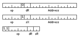
Here, then, are the instruction formats for a small-scale computer which still handles the usual big-computer data types.

It is envisaged that we are dealing with a computer which has four index registers, each one 24 bits in length, although only the last 15 bits are used when indexing is performed, four general registers, each one 36 bits in length, and four floating-point registers, each one 60 bits in length.
Regular memory reference instructions could use any of the four general (or floating-point, as applicable) registers as their destination, while indexed memory-reference instructions would always have register 0 as their destination. Note that index register 0 would also operate as a normal index register, unlike the convention in some architectures.
Memory addresses indicate a particular 12-bit storage unit in memory.
The opcodes would be the following:
000001 C   Compare
000010 L   Load
000011 ST  Store
000100 A   Add
000101 S   Subtract
000110 M   Multiply
000111 D   Divide

001000 N   AND
001001 O   OR
001010 LX  Load Index
001011 STX Store Index
001100 X   XOR
001101 (conditional jump instruction)
001110 MX  Multiply Extensibly
001111 DX  Divide Extensibly

010000 XS  XOR Small
010001 CS  Compare Small
010010 LS  Load Small
010011 STS Store Small
010100 AS  Add Small
010101 SS  Subtract Small
010110 NS  AND Small
010111 OS  OR Small

011000 (subroutine jump instructions)
011001 CF  Compare Floating
011010 LF  Load Floating
011011 STF Store Floating
011100 AF  Add Floating
011101 SF  Subtract Floating
011110 MF  Multiply Floating
011111 DF  Divide Floating

100000 IS  Insert Small
100001 CI  Compare Intermediate
100010 LI  Load Intermediate
100011 STI Store Intermediate
100100 AI  Add Intermediate
100101 SI  Subtract Intermediate
100110 MI  Multiply Intermediate
100111 DI  Divide Intermediate

101000 ULS Unsigned Load Small
101001 CD  Compare Double
101010 LD  Load Double
101011 STD Store Double
101100 AD  Add Double
101101 SD  Subtract Double
101110 MD  Multiply Double
101111 DD  Divide Double
Since a mode bit changes the standard integer type from 36 bits to 24 bits, there are no insert or unsigned load instructions for the 24 bit type; in the 24-bit integer mode, all instructions leave the 12 most significant bits of the four general registers unchanged, and the integer ALU behaves as a 24-bit ALU.
As there are only 48 operations, 11 in the first two bit positions moves the opcode over two bits, and indicates a register to register operation.
The conditional jump instructions would use the next three bits to indicate the circumstance under which a jump is performed:
001101001 JG  Jump if greater
001101010 JE  Jump if equal
001101011 JGE Jump if greater or equal
001101100 JL  Jump if less
001101101 JNE Jump if not equal
001101110 JLE Jump if less or equal
001101111 JMP Jump
The jump to subroutine instruction stores the return address in the index register selected as the destination register, and cannot be indexed. When the index bit is set with the same opcode, an indexed unconditional jump is the instruction, and such a jump with an address displacement of zero can be used to return from a subroutine.
0110000 JSR Jump to Subroutine
0110001 XJ  Indexed Jump
An indexed jump could also be used to jump into a series of jump instructions, although the index would have to be an even number, so a pre-indexed indirect jump is not needed for choosing one of multiple alternatives.
Also, instructions starting with 1111 would be used for things like shift instructions.
Floating, Intermediate, and Double would be floating-point types that are 36, 48, and 60 bits long respectively.
Short would refer to 12-bit integer operands, and the operations without a type in their mnemonic would operate on either 24-bit integers or 36-bit integers, depending on the setting of a mode bit; some programs need 36-bit integers, and some only need 24-bit integers.
A computer such as this would easily satisfy many computing needs; a 32K contiguous address space would be well suited to compiling and running FORTRAN programs of reasonable size.
Fitting memory-reference instructions into 24 bits and register to register instructions into 12 bits makes highly efficient use of memory for programs as well.
But while 32K 12-bit words is space enough for many programs, it is still constricting for some. One can assume that there might be a 24-bit or 36-bit register containing the address of the 32K area in which a given program runs.
Using the index registers as base registers for distant accesses is one possibility; but better compatibility would be obtained by reserving some of the opcodes beginning with 1111 for prefix symbols, particularly as one important use for a larger address space would be the ability to operate on arrays larger than 32K in size, so both an index and a base are needed.
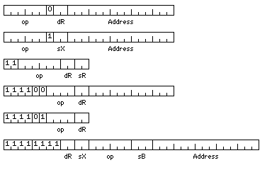
To increase the address space from being enough to reach 32K 12-bit storage cells, or 48K bytes, to being enough to reach 96 Gigabytes, by using 36-bit addresses, and in addition to show the formats of operate instructions that would be needed even without address extension, the instruction formats can be augmented as shown below:

Let
11111111ddxx
prefix an instruction to indicate that the contents of one of eight 36-bit base registers is added to its address. The bits marked xx indicate one of three 36-bit long index registers, or, if 00, indicate no indexing is present, and the bits marked dd indicate the destination register in the normal way.
The LDX and STX instructions still refer to the normal index registers, but in this format, opcodes with the first two bits equal to one are allowed, adding the following operations:
110000 LB   Load Base
110001 STB  Store Base
110010 LLX  Load Long Index
110011 STLX Store Long Index
Further, the shift instructions can be defined:
1111000000rr LSR Logical Shift Right
1111000001rr ASR Arithmetic Shift Right
1111000010rr LSL Logical Shift Left

1111000100rr RR  Rotate Right
1111000101rr RL  Rotate Left
where rr specifies the register whose contents are shifted, and the shift count is in the next 12 bits of the instruction.
and a number of operate instructions can be defined:
1111010000rr CLR   Clear
1111010001rr INC   Increment
1111010010rr INV   Invert (one's complement)
1111010011rr NEG   Negate (two's complement)

1111011111ci MODE  Mode set
The mode set instruction controls whether 6-bit or 12 bit characters will be used, based on whether the bit c is 0 or 1 respectively, and whether 24-bit or 36-bit integers will be used, based on whether the bit i is 0 or 1 respectively. The instructions affected by the character size will be described below.
The contents of base register zero will be added to addresses in the 24-bit memory reference instructions, so that these wouldn't be limited to the beginning of the virtual address space; programs which are not cognizant of the 36-bit memory-reference instruction format would also not be cognizant of the eight base registers, and compatibility is maintained.
Simply because register to register instructions are 12 bits instead of 16 bits, and memory reference instructions are 24 bits instead of 32 bits, while there are some limitations, such as having four general registers instead of eight or sixteen, it should not be thought that this architecture is not powerful or extensible.
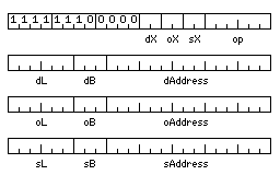
The diagram below illustrates the format

of a 96-bit long three-address instruction, used for packed decimal, string, and vector operations.
The opcodes for this instruction type would be:
000010 MV  Move

000100 A   Add
000101 S   Subtract
000110 M   Multiply
000111 D   Divide

001000 N   AND
001001 O   OR

001100 X   XOR

010000 XS  XOR Small

010010 MVS Move Small

010100 AS  Add Small
010101 SS  Subtract Small
010110 NS  AND Small
010111 OS  OR Small

011010 MVF Load Floating

011100 AF  Add Floating
011101 SF  Subtract Floating
011110 MF  Multiply Floating
011111 DF  Divide Floating

100010 MVI Move Intermediate

100100 AI  Add Intermediate
100101 SI  Subtract Intermediate
100110 MI  Multiply Intermediate
100111 DI  Divide Intermediate

101010 MVD Move Double

101100 AD  Add Double
101101 SD  Subtract Double
101110 MD  Multiply Double
101111 DD  Divide Double

110010 MVP Move Packed

110100 AP  Add Packed
110101 SP  Subtract Packed
110110 MP  Multiply Packed
110111 DP  Divide Packed

111010 MVC Move Character

111100 PK  Pack
111101 UPK Unpack
111110 T   Translate
With the Packed and Character types, the length represents the number of digits in a single number, or the number of characters in a single string. With the other types, the length represents the length of a vector, and the source and operand lengths can only be either the same as the destination length, or equal to one for a constant operand. A value of 0 in a length field represents a length of 64 items.
The Move, Pack, and Unpack instructions are two-address, so only source and destination addresses are used, and the instruction is 72 bits long instead of 96 bits long.
For the translate instruction, the operand address is that of the translate table. The length is ignored, since a translate table has either 64 or 4,096 entries depending on the character length mode in use.
On the previous page, a word length of 36 bits was chosen because a bus width of four times that word length would permit fetching any aligned 36-bit, 48-bit, or 72-bit operand in a single memory access.
Here, we build up 36-bit, 48-bit, and 60-bit operands from individual 12-bit cells, and the only way to handle aligned operands of these three sizes would be to have a very wide 720-bit bus. How could we avoid frequent penalties for fetching operands which are not aligned, at least not with respect to the memory layout in use?
If a 12-bit wide bus to memory is used, the issue does not arise; a 60-bit operand will take five fetches to load, no matter where it starts.
But how to deal with this for a wider memory? One way would be this: to have a 96-bit wide data bus, but to divide it into two halves, each with its own address bus. Then, a 60-bit wide value starting on any 12-bit boundary could be fetched in a single operation, either by fetching the 48 bits at the same address in the left and right halves, or by fetching the 48 bits in the left half at an address one greater than the 48 bits in the right half.
It is felt that a 36-bit floating-point format will be significantly more useful than a 32-bit one in more cases, and that a 48-bit floating-point format will also further reduce the need for double precision. As well, a 60-bit format should satisfy the requirement for double precision, when it genuinely arises.
However, the IBM 360 had 64-bit double precision, and with the model 81, it still introduced a 128-bit extended precision floating-point type, and more recently, one has been added to the IEEE 754 standard, even though that already provided for an 80-bit floating-point type.
Given that a 12-bit word is the basic unit, of 36-bit, 48-bit, and 60-bit floating-point types, only the 48-bit type is a power-of-two multiple of the basic unit; the architecture above, with dual 48-bit buses, as it allows 60-bit quantities to be unaligned, can also cope with unaligned 48-bit quantities.
It could also handle 96-bit floating-point numbers, as long as they were aligned on 48-bit boundaries. The long instruction format for distant references allows the first two bits of an opcode to be 1. A few opcodes of that form have been added above to allow access to the new registers required for those instructions. Available opcodes still exist to provide a complete set for 96-bit floating-point numbers:
111001 CE  Compare Extended
111010 LE  Load Extended
111011 STE Store Extended
111100 AE  Add Extended
111101 SE  Subtract Extended
111110 ME  Multiply Extended
111111 DE  Divide Extended
It again seems to me that 96-bit floating point will be both quite long enough, and that it will be rarely used, so having these instructions only in the longer instruction format will be satisfactory.
Perhaps another mode bit will be required, to allow the character instructions to be replaced by extended precision vector operations, if this type is added.
It may be noted that a 12-bit program status word would suffice to hold the carry bit, condition codes, a user/supervisor bit, and the two mode bits for character and integer lengths. But to support IEEE 754 type operation, even with different lengths, the status word would have to be expanded, perhaps only to 24 bits.
In an interrupt, the program counter, the program status word, and base register zero would all have to be automatically saved before the interrupt service routine could begin; it could store everything else using conventional instructions without disturbing anything, although automatically saving an index register and replacing it with a stack pointer in memory as well would simplify dealing with multiple levels of interrupts that were dispatched initially to the same interrupt service routine. If an interrupt service routine can only be interrupted by higher-priority interrupts which have their own interrupt vectors, then they can have their own static locations to store saved information, and this would not be needed.
However, in the more ambitious case where a 720-bit block is used as the basic unit, 96-bit floating point numbers would not be possible to align. Remaining with multiples of 12 bits, either 72 bits or 120 bits would be possible. If that condition is dropped, in addition to dividing a 720-bit block into six 120 bit numbers or ten 72 bit numbers, eight 90-bit numbers or nine 80-bit numbers would also be possible as alternatives. Following IEEE 754, 16 of those bits would be used for the sign and the exponent. It might be useful, however, to chop off the last five bits of the mantissa, and use them instead to indicate additional data that might be kept in the floating point registers:
Two bits to indicate the precision of the number currently stored:
00  36 bits
01  48 bits
10  60 bits
11 120 bits
and three bits indicating how the last result was rounded, or if the result is a NaN (Not a Number):
000 exact
001 rounded down        (higher than nominal value)
010 rounded up          (lower than nominal value)
011 rounding indefinite (previous operation did not produce exact rounding)
100 value indefinite            (i.e. 0/0)
101 plus infinity
110 minus infinity
111 infinite, but sign unknown  (i.e. 1/0)
If memory is divided into blocks of 120 bits, simple binary divisions would be 15, 30, and 60 bits. To treat it as being composed of parts 12 bits in length would require dividing a block of 120 bits into ten parts, or a block of 720 bits into sixty parts.
How can addressing be prevented from being a nightmare?
Multiplying by three requires one shift and add. So if base registers contain the number of a 720-bit block in memory, this can be converted to the address of a 120-bit word in external memory through multiplication by three and an additional shift.
If an aligned 60-bit double-precision number is addressed, it can be referenced using a raw address, then, which requires only shifting to obtain the address of a 120-bit word. Matters can be equally simple for addressing 30-bit or 15-bit entities, which is an argument for using 30-bit integer variables, and instructions composed of 15-bit halfwords in this case.
What of 36-bit and 48-bit floating-point numbers, however? A hardware divide-by-five circuit could deal with indexing and addressing in the case of such numbers. And 60-bit floating-point numbers could also be addressed in an alternate fashion within that system.
To simplify matters, since a multiply by three circuit is seen as needed so as to make the architecture independent of the use of an external 120-bit bus instead of the ideal 720-bit bus, thus avoiding the need for a divide by three circuit in the latter case, one can think instead of a divide by fifteen circuit. In binary, fifteen is 1111, and, thus, one-fifteenth is 0.11111111... in hexadecimal notation.