It isn't necessary to use only memory words with power-of-two sizes and still use standard memory parts. One could use three 64-bit wide memory buses to use 24 or 48 bits as the basic unit. Or one could use 64 bit wide memory parts, but use 16 of those bits for a DEC-TED error correcting code.
But this is more challenging in that we are now dealing with a word size that is very different from the series 8, 16, 32, and 64 rather than one that is just slightly larger at each level. So one must try to make the instructions significantly shorter to avoid ending up making them significantly larger.

What I have done is that I have chosen to make an instruction format that strongly resembles that used for classic 24-bit computers. So every instruction is only 24 bits long.
Is there really enough opcode space to pull that off? And wouldn't having the instructions use memory instead of registers be inefficient?
Well, I will admit that there isn't enough opcode space to handle all the data types that I would like to handle with separate opcodes. Thus, it will be necessary to select which data types are to be used, but at least a reasonable number of different types can be used at once.
As for inefficiency, there is enough opcode space reserved for operate instructions, as we will soon see, that register-to-register instructions can be provided.
This means that, as well, another mode in which the memory-reference instructions are limited to loads and stores, so that all the types are available at once, can be provided, but we will also see why this is not made the default, or, indeed, the only mode.
Indirect addressing is provided; address constants have the form:

so they can be 24 or 48 bits long, providing either a 20-bit address or a 44-bit address in units of 12 bits.
Now to get to the details of how these instruction formats are to lead to a workable design.
These are the instructions that perform arithmetic operations on data types which are aligned on 24-bit boundaries.
The first sixteen of the opcodes will often operate on 24-bit integers:
000 0 SW Swap
002 0 CS Compare and Skip
004 0 LD Load
006 0 ST Store
010 0 AD Add
012 0 SB Subtract
014 0 MP Multiply
016 0 DV Divide
020 0 IN Insert
022 0 UC Unsigned Compare and Skip
024 0 UL Unsigned Load
026 0 XR XOR
030 0 AN AND
032 0 OR OR
034 0 MX Multiply Extensibly
036 0 DX Divide Extensibly
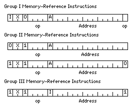
The I bit indicates indirect addressing; the two X bits are either 00 for a normal memory access, or they indicate which of three index registers is used for an indexed memory access. The bit marked A indicates whether accumulator A or accumulator B is the destination register for the instruction, and the letter A or B is suffixed to the instruction mnemonic as shown above.
The second sixteen opcodes in Group I are distinguished by having the last bit of the instruction to 1.
These instructions work with different data types depending on the mode selected.
In one mode, they will work with 48-bit integers.
In another mode, they will work with 96-bit extended precision floating-point numbers. In this case, the sixteen opcodes used will include opcodes for unnormalized arithmetic instructions, as the extended precision format does not have a hidden first bit.
In a third mode, the first eight of these instructions will work with 48-bit intermediate precision floats, and the second eight will work with 72-bit classic double precision floats.
It is also possible to have the first sixteen opcodes work with 48-bit integers, with any of the options involving floating-point types for the second sixteen opcodes.
This group of memory-reference instructions consists of those which perform arithmetic operations on data types which are aligned on 12 bit boundaries.
The first illustration under that heading shows the case where indirect addressing is not used; here, the address field is lengthened on the right by one bit, so the last bit of the instruction cannot be part of the opcode in this group.
The second illustration shows what happens when indirect addressing is used.
Since address constants are aligned on 24 bit boundaries, the final bit of the instruction is always zero; a one in that position is instead used to indicate a Group III memory-reference instruction.
So there are only sixteen available opcodes rather than thirty-two for this group of instructions.
In one mode, they operate on 12-bit integers.
In another, the first eight of these instructions operate on 36-bit single precision floats, and the second eight operate on 60-bit double-precision floats.
These instructions fit into the left-over space resulting from the way the Group II memory-reference instructions are laid out. Thus, the first bit of the instruction, normally used for the indirect bit, is always a one. So the bit used to indicate which accumulator is used is instead used to indicate indirect addressing.
The instructions in this group are:
440 1 JMP Jump
442 1 JSR Jump to Subroutine
444 1 ISZ Increment and Skip if Zero
446 1 XSI Execute Supplementary Instruction
450 1 LAD Load Address
452 1 LAX Load Address to Index
The XSI instruction has an instruction in 48-bit format as its operand; this allows access to data types outside the current mode, as well as allowing more complicated instructions, such as string instructions which require two addresses.
Some opcodes in this group are left unused to allow space for operate instructions.
And the operate instructions would look like this:
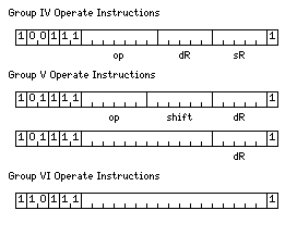
The Group IV operate instructions provide 128 possible opcodes for register-to-register instructions.
The Group V operate instructions include several types of shift, and also instructions which dedicate one bit to operations such as clearing a register, inverting its bits, and incrementing the register, allowing combinations to indicate things such as a two's complement of the register, or setting its contents to 1.
The Group VI operate instructions include those for choosing the modes for the memory-reference instructions.
Programs can be granted virtual address spaces of three sizes: 32 K memory units of 12 bits, with a 15-bit virtual address, 1 M memory units of 12 bits, with a 20-bit virtual address, or 16 G memory units of 12 bits, with a 44-bit virtual address.
The first three bits of a 14 or 15 bit address field in an instruction select one of eight page registers to supply the rest of the address.
If a program is granted a 32K virtual address space, it does not have unprivileged access to those page registers.
If a program is granted a 1M virtual address space, it has access to eight page registers which are eight bits in length, so that when prepended to the remaining 12 bits of a 15-bit address field they will create an address that is 20 bits in length, the same length as the address portion of a one-word address constant.
If a program is granted access to a 16G virtual address space, it has access to two sets of eight page registers.
The first three bits of a 14 or 15 bit address field in an instruction selects one of eight page registers that are 32 bits long, so that when prepended to the remaining 12 bits of a 15-bit address field they will create a 44-bit address.
The first three bits of the 20-bit address portion of a single-word address constant selects one of eight page registers that are 27 bits long, so that when prepended to the remaining 17 bits of the address portion of a one-word address constant they will create a 44-bit address.
So far, what we have seen is an old-fashioned architecture that involves memory in every instruction. For large memories which must be in external DRAM, this will not be very efficient when implemented in current technologies.
The situation can be improved somewhat by using some of the available opcode space for operate instructions to provide register-to-register instructions.
Another mode of operation would then take the Group I and Group II memory-reference instructions, and allocate only load and store instructions for as many data types as possible to their opcode space.
This would lead to operation with shorter instructions of 24 bits instead of 32 bits, and the wide selection of data types envisaged, in a manner similar to current RISC chips.
Accumulators A and B would be registers 0 and 1 in the register banks provided.
However, even if there was enough opcode space for 32 registers, so as to match a RISC design - and if one uses two-address instructions instead of three-address, and remembering that the two index register bits are available for opcode use, that should not be a problem - that still doesn't eliminate the need to incur the overhead of an out-of-order design, because conventional RISC designs need to be implemented in OoO fashion these days, since 32 registers doesn't allow enough instruction-level parallelism to be explicitly specified to handle the level of pipelining needed for currently-desired high clock speeds.
And so a "fast mode" can also be applied to this design.
In that mode, the first three bits of the address field of a Group I or Group II memory-reference instruction are a thread ID. The A and B integer and floating-point accumulators belong to sets of sixteen accumulators, a pair of which are selected by the thread ID. The memory address refers to a small internal memory - actually special a direct-mapped level 1 cache, so that instead of loading and saving it, one simply loads a pointer to the memory it refers to.
The allocation of these accumulators to the thirty-two registers used in the operate instructions would be as follows:
Thread ID   Accumulator Name   Register
  000             A                0
  000             B                1
  001             A                4
  001             B                5
  010             A                8
  010             B                9
  011             A               12
  011             B               13
  100             A               16
  100             B               17
  101             A               20
  101             B               21
  110             A               24
  110             B               25
  111             A               28
  111             B               29
so the thirty-two registers would be divided into eight sets of four, the first two of which serve as the two accumulators for each thread.
Before coming up with this architecture, another idea I was working on was one with instruction formats like this:
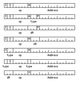
where it would be possible to select between a variety of modes which provided different numbers of accumulators and index registers.
Thus, when someone suggested that having two accumulators, following the 6502 as an example, was not enough, I was inclined to agree: the Data General Nova provided four registers as a minimum to get the benefits of having general registers, and even the System/360 originally had only four floating-point registers (as, unlike the sixteen general registers, floating-point registers didn't also serve as index and base registers).
And so I came up with this:

For Group I and Group II memory-reference instructions, one could go to four registers simply by having only one bit indicate the use of a single index register. Shrinking the index register field, though, would have no point for the Group III memory-reference instructions, which don't operate on a destination register.
For the Group I memory-reference instructions only, it would be possible to go further, to eight registers, by getting rid of the indirect bit. After all, indirect addressing is considered archaic these days. But that only works for those instructions, because for the Group II instructions, that work on data aligned on 12-bit boundaries, the fact that indirect addresses are still aligned on 24-bit boundaries was exploited to make room for the Group III memory-reference instructions.
Unfortunately, I fear that this is a bit too much non-orthogonality to be worthwhile, although if one sticks to the modes with either two or four registers, just omitting the one with eight registers, it might not be too bad, because then the only non-orthogonality is that the Group III instructions have extra indexing capabilities in the four-register mode.
Because of the large number of data types it is desired to handle, selecting which types are to be used seems to be necessary to also allow enough addressing modes and enough address space in instructions.
There are thirty-two available opcodes for Group I memory-reference instructions.
In order to have the complete basic set of instructions for all the data types these instructions handle, the requirement is:
This is a total of 64 opcodes, twice as much, and so one bit needs to be taken away.
There are sixteen available opcodes for Group II memory-reference instructions.
In order to have the complete basic set of instructions for all the data types these instructions handle, the requirement is:
This is a total of 32 opcodes, twice as much, and again, one bit needs to be taken away.
There are a number of ways to take one bit out of the instruction format.
Even more radical, however, would be to note that since three index registers can be specified in an indirect address, one could drop the index register field entirely, and still double the number of opcodes, and have four accumulators.
This would mean that indirection would always have to be used when indexing is desired. That would seem to be an unacceptable overhead.
But this is needed in any case where arrays don't fit into the 32K of memory that instructions can address directly. And that suggests an even more radical idea: shrink the address field, in that case, from 15 bits to 12 - and allow instructions to both use all the data types, and to refer to all thirty-two registers.
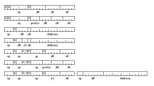
Here is what I came up with after struggling to fit a modern RISC architecture into 24 bit words instead of 32 bit words:
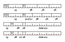
I thought that there was plenty of space for the register-to-register instructions, so instead of one bit to indicate them, I took two; but with a bit needed to indicate whether an instruction affects the condition codes, that left only six bits for the opcode.
It is envisaged that since integer arithmetic takes fewer cycles than floating-point arithmetic, 32 integer registers are adequate, but 128 floating-point registers are useful - for removing the need for out-of-order execution. So the 128 floating-point registers are divided into eight groups of sixteen to permit them to be used.
Obviously, though, there are options here if more opcodes are needed: two-register instructions instead of three-register instructions are usually quite satisfactory.
But the memory-reference instructions are still far too constrained; only six opcodes remain available for them. Load, Store, Load Floating, Store Floating, Jump, and Jump to Subroutine presumably - with the lengths of the integer and floating-point numbers in use set in another instruction. At least, the Jump instruction can be a conditional jump, using the destination register field for that, so conditional skip instructions need not be taken from the ancient days of computing.
One could switch to a 12-bit address field from a 15-bit one, or remove the bit that allows sixteen, rather than four, registers to be the destination of a non-indexed load. So there are ways to push this into something that might be usable, although each option comes at a heavy price.
Still, some opcode space remains available, and it can be put to use:
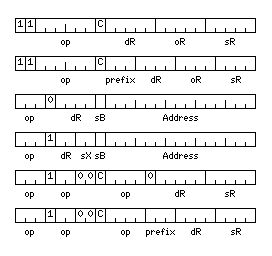
Since there are sixteen destination registers for the mode where indexing is not available, assuming three registers used as index registers, with 00 in that field indicating no indexing, there is no need to have a second way to refer to four of those sixteen registers.
So, instead, we can fit in two-register instructions with a nine-bit opcode field (split into three pieces) which can take on 384 values. In the case of two-register integer instructions, one bit remains unused, allowing for further expansion. However, if the instructions are all to be only 24 bits in length with no exceptions, the severe limitation on memory-reference instructions remains a problem.
So, since memory-reference is infrequent and slow, unlike register operations, incurring the penalty of variable-length decoding for those instructions does not seem too terrible:
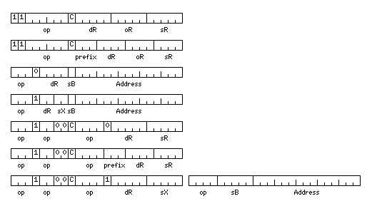
thus allowing a fairly large number of instructions which permit 31 of the 32 integer registers to be used as both index and base registers.
It is envisaged that in short-form memory-reference instructions, integer registers 1, 2, and 3 would be the index registers, and integer registers 30 and 31 would be the two base registers (in that case, 0 in the sB field would not indicate absolute addressing).
This two-word format could only be selected when the first nine bits of the opcode field correspond to an integer two-register instruction. But these instructions could still be floating-point instructions; in that case, the destination register field would indicate a floating-point register the number of which is a multiple of four; two zeroes would be implicitly appended on the right.
Similarly, in the short format memory-reference instructions, for the indexed ones, the two-bit destination register field would indicate integer registers 0, 8, 16, and 24 or floating-point registers 0, 32, 64, and 96. For the non-indexed ones, the four-bit destination register field would indicate an even-numbered integer register, or a floating-point register the number of which is a multiple of eight.
Actually, for the long-format memory-reference instructions, there is enough opcode space that it isn't really necessary to put up with a limitation on the destination register for them; the fields just need to be re-ordered slightly, as there is not really an urgent need for all the opcode bits available:
