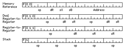
Further thoughts on the matter have led me to a design inspired by microprocessors such as the Texas Instruments TMS320C signal processing chip:

The four instruction formats shown in this diagram are:
For the memory reference and dual register operations, the first eight of sixty-four registers are used; the single register operation provides access to the full register pool.
Since stack operations are naturally dependent on each other, the five operations in a stack operation will refer to five separate stacks - or this format will be used for some other manner of allowing the number of operations specified in 32 bits to be increased.
Incidentally, of course the stacks will be part of the processor, with their locations implemented in a similar manner to registers, and they will be short, perhaps eight or at the most sixteen elements each.
Normally, in each cycle, a 256 bit long bundle of eight instructions is fetched and executed.
If an instruction uses the same ALU or other computational facility as an earlier instruction in the same bundle, the first bit of the instruction is set to 1 to split the bundle at that point.
The first bit of the first instruction in a bundle, on the other hand, is used to indicate the presence of a dependency.
It is, of course, normal that instructions in a program will act on results from previous instructions executed in the same program. Thus, it is not desired that every time a dependency is found, the entire pipeline must be flushed.
I avoid this by handling the dependency bit as follows:
Each time the dependency bit is a 1, it indicates the start of a dependency region.
The instructions within a single dependency region may not be dependent on each other, or on the instructions in the immediately previous dependency region. But they may depend on the results of the instructions in the one before.
In this way, without having to include enough bits to explicitly specify which instruction's results are being depended on by a later instruction, only the oldest instructions in the pipeline need to be flushed, not later ones on which a new instruction is not dependent.
There will be a special instruction of the single register-register format to indicate that the pipeline does need to be fully flushed, and another one to indicate the start of the first dependency region so that the first dependency bit set to 1 that is subsequently encountered will only delimit what future instructions will depend on, and will not cause the pipeline to be even partially flushed on its own account.
A sub-instruction of the double register-register format will be used to test the contents of a register, and set a flag bit, specified by the destination register field, based on whether they meet a criterion.
Conditional jump instructions will branch if a flag bit is set; this is the scheme used on the STRETCH computer. They will be dependent on the instruction that set the flag bit they use. But the instruction bundle to which a branch is made (or the immediately following instruction bundle that is not executed because of the branch) will not be (deemed to be) dependent (for the purpose of setting the dependency bit) on the jump instruction, since by the time the correct instruction bundle is fetched, that dependency must already have been resolved.
There will be eight flag bits, specified in the destination register field both of the test instruction that sets them, and the jump instruction that references them.
Ideally, though, having just one bit to indicate dependency does present a problem. Since the bit serves two purposes, indicating a dependent instruction, and indicating an instruction that is being depended on, then there will clearly be cases where the bit is set in order to prevent a future case where it is set from flushing too much of the pipeline when there is no dependency in the block in question.
This problem may be more apparent than real, simply because the bit will almost always be set; it will be hard enough to arrange the instructions so that each instruction has no dependencies on (up to) the previous 15 instructions, never mind achieving even longer dependency-free sequences.
One option to deal with this while limiting waste would be to lengthen the instructions from 32 bits to 36 bits. Seven of them could fit in a 256-bit instruction bundle, with three bits left over, two of which could be used to indicate dependencies; one to flag the block containing a dependent instruction, and one to indicate the preceding block after the one on which the instruction depended.
An even simpler alternative, however, is obviously available.
If the stack format of instructions, which was noted as being likely to be grossly impractical, is dropped, then the first prefix bit in the instruction is always zero for the remaining instruction formats, and thus can be used as a second flag bit without changing anything else in those other formats.
In that case, the second flag bit would indicate a dependent instruction.
The first flag bit would indicate an ALU conflict in any 32-bit sub-instruction except the first one in a block. In the first position, if it is set, it would indicate the start of a series of blocks in which there are no dependencies; when a dependency bit is set, that means a dependency on an instruction preceding that series of blocks.
When the first flag bit is set in the first sub-instruction, and the second flag bit is set anywhere in the block, now that means the dependency is indicated as being in the immediately preceding block.
And, as a nine-bit opcode should be adequate for the single register-to-register instructions, the possibility of including additional instruction formats if required is not eliminated by having a second flag bit:
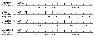
One possibility would be to change the stack format from having five six-bit opcodes to having three nine-bit opcodes. Another, shown in the diagram above, would be to allow memory-reference instructions with longer opcodes in an alternate format omitting the index register field. However, due to the additional prefix bits, this only expands the opcode field to six bits from five.
As some discussions have led me to discover that the idea of combining a stack architecture with RISC/VLIW-level performance goals has, in fact, been tried, and it is not as perverse as I thought, I came up with another variation:
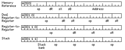
in which the stack instructions now refer to four stacks, so each opcode in the instruction affects a different stack, but there is also a stack bank field, shown here as three bits long, so that there are actually 32 different stacks in use. This would permit stack instructions to be interspersed with a high enough interleaving factor to permit them to be a major part of a program without overly frequent waits for the pipeline to empty before a dependent operation can start.
Also, to reduce dependencies, an instruction to change the eight registers referred to in most instruction formats from among the sixty-four in the single register instruction format from the first eight to one of the seven other groups of eight may be provided. Although it would affect the execution of subsequent instructions, provision could be made, as it doesn't perform calculations, but merely places an immediate operand in a special register, that it is exempted from dependency requirements, as it is guaranteed to affect the instructions that commence in the very next cycle after that instruction commenced. Which would mean that only the ALU conflict bit would need to be set if it was desired to have such an instruction affect following instructions in the same instruction bundle.
On further thought, to reduce dependencies, ideally the two register-to-register instructions in a dual register-to-register word should refer to different register windows, so there should be two of those special registers. Or three, so that the memory reference instructions aren't tied to either the first or the second operation in such a word.
And that suggests one more change:
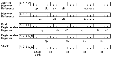
Since most memory reference instructions aren't indexed, there's wasted space that can be used to remove the restriction of unindexed memory references to loads and stores.
If we assume only the usual data types are used, then there is enough opcode space for all the normal loads and stores for the indexed memory-reference instructions, with another important instruction:
ad00 0000 LB     Load Byte
ad00 0001 STB    Store Byte
ad00 0010 LH     Load Halfword
ad00 0011 STH    Store Halfword
ad00 0100 L      Load
ad00 0101 ST     Store
ad00 0110 LL     Load Long
ad00 0111 STL    Store Long
ad00 1000 LF     Load Floating
ad00 1001 STF    Store Floating
ad00 1010 LD     Load Double
ad00 1011 STD    Store Double
ad00 1100 LE     Load Extended
ad00 1101 STE    Store Extended
ad00 1110 LA     Load Address
With a convenient way to put the effective address of a full memory-reference instructon into a register, making instructions in the other formats into memory-reference instructions that use registers as pointers is possible.
Thus, the 32-bit register-to-register instruction format could be used for a character translate instruction that obtains the string length from register 0, and indicates three pointer registers for the source string, the translate table, and the destination string.
That, of course, goes a long way away from the design's DSP roots, and recalls another architecture that used 32-bit instruction words, the SDS/XDS Sigma series of computers.
More recently, thinking even more about the issues involved, I've come up with this:
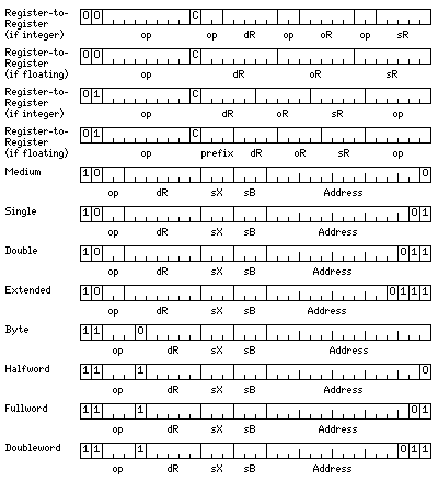
There are 32 integer registers, but 128 floating-point registers, on the basis that floating-point instructions take more cycles than integer instructions, and therefore more registers are needed to allow enough simultaneous calculations to be interleaved to eliminate the need for a complicated and expensive out-of-order implementation.
The memory-reference instructions have space for eight base registers and seven index registers. Of the 32 integer registers, numbered from 0 to 31, the seven index registers will be integer registers 1 through 7 (with zero in that field indicating the instruction is not indexed), and the eight base registers will be integer registers 24 through 31.
When the base register field contains 000, array mode will be used: so register 24 would point to an area containing the addresses of arrays, and thus addressing will be indirect, with post-indexing when the index register field is nonzero. This facilitates the compilation of programs that use multiple very large arrays.
In order that no more than half the opcode space is taken up by memory-reference instructions, it has been necessary to employ the SEL 32 trick of only allowing aligned operands, and then taking advantage of the unused least significant bits of the address field to distinguish between data types.
It is because memory-reference instructions provide full index-base adressing, without the need for an address set-up instruction, that providing sufficient opcode space for them posed some difficulty, requiring effort to limit them to half the opcode space.
For floating-point numbers, the operations provided would be:
00 Load
01 Store
10 Exchange
11 Compare
For integers, the operations are:
000 Load
001 Store
010 Exchange
011 Compare
100 Load Unsigned

110 Insert
The compare instruction, unlike the register-to-register arithmetic instructions, does not require a C bit to indicate whether it is allowed to change the condition codes, since doing so is its only result, and hence its only purpose.
As well, the unused opcodes would be used for additional instructions:
Note that two formats of register-to-register instruction are present. One allows for full general use of the 128 floating-point registers, in that format there are 64 times as many opcodes for integer instructions as for floating-point instructions.
The other allows an equal number of integer and floating-point instructions by dividing the 128 floating-point registers into eight groups of sixteen, and requiring that all the registers specified belong to the same group.
Instructions such as shift instructions, instructions in which two rather than three registers are specified, and so on, would also belong to this group.
In order to provide a completely general instruction set, however, some instructions longer than 32 bits would have to be allowed, leading to a variable-length encoding:
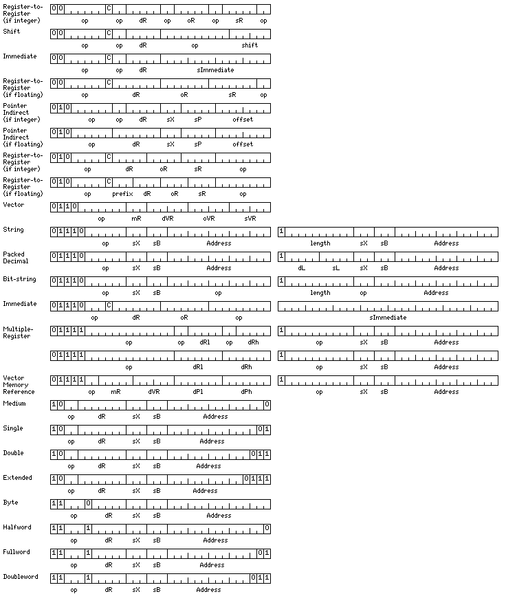
Here, it is shown how the basic register format can be slightly modified to include shift instructions.
Instructions allowing arithmetic between vector registers can fit in 32 bits.
To allow an adequate size for the opcode field, the mask register field is three bits long: 000 indicates no masking; the other values refer to integer registers 9 through 15.
Character string and packed decimal instructions like those of the System/360 are shown for completeness. However, at least the packed decimal ones are not intended to be implemented. Those weren't a mistake on the 360, because the lower machines in that series were intended as successors to the 1401, and the CPU was slower than memory; in fact, in the 360/30, microprogram steps were read from ordinary core memory - as well as core being used for the registers. So operands in memory instead of registers didn't slow anything down there, even if those instructions did fare poorly on higher-end systems such as the 360/75.
While they weren't a mistake then, they would be now, since memory is much slower than the CPU in typical microcomputers. Instead, since there are many opcodes for register-to-register operations, it is anticipated that there will be instructions that perform arithmetic between the integer registers, interpreting their contents as packed decimal numbers.
Load multiple and save multiple instructions, handy for context switching, need to be longer than 32 bits, even though they fit in that length on the System/360, because we are dealing with register files with 32 or 128 registers, not just 16 registers.
As they're expanded all the way to 64 bits, there is enough extra space so the same format can accomodate the instructions used to load and store the contents of vector registers.
In response to some suggestions I have recieved, I have added two modes to the architecture.
The pointer indirect mode performs loads and stores from memory, without alignment restrictions. Instead of a base register, there is a pointer register, intended to point to the variable being dealt with. A short displacement field, labelled "offset", allows reference to things like the real part of a complex variable; elements of data structures today have taken on greater importance due to the popularity of object-oriented languages like C++.
As well, since I have 64-bit instructions, some instructions with 32-bit immediates have been added, as these avoid the need to fetch constant operands from memory; instead, they're obtained from the stream of data prefetched to facilitate instruction decoding. This is particularly important once you consider the fact that modern DRAM chips are well suited to providing data from multiple consecutive addresses, and have significant overhead when switching to a new address.
The following, on the other hand, is an indulgence of my own that I present despite all outside advice:
An alternate mode changes the formats of the floating-point memory reference instructions to the following:
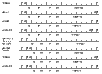
The first four lines of the diagram show the formats of the conventional floating-point memory reference instructions. The destination register field has been shortened by one bit, and so these instructions can only load to, or store from, even-numbered registers.
The last four lines of the diagram show the formats of floating-point memory-reference instructions that refer to memory as though it were divided into 12-bit units instead of 8-bit bytes; this allows the use of floating point numbers the sizes of which may be more optimal in some cases.
For these instructions, the base register field refers to registers 16 through 23 instead of registers 24 through 31; the contents of the base register are still a normal byte address. Once again, 000 indicates array mode, and thus register 16 will point to a list of the addresses of large arrays.
The sum of the contents of the index register (if used) and the value in the address field, however, is multiplied by three, and the result is taken as a nybble address. Thus, for these instructions, memory is divided into units of twelve bits.
This is intended to allow load/store instructions for the following data types:
as described elsewhere; following the IEEE 754 format, but with one extra exponent bit for single precision, and two more exponent bits for intermediate precision than for 32-bit single precision.
Here, to allow enough opcodes, only 16 destination registers are available; the contents of that field are multiplied by 8 (shifted left three places) to indicate the floating-point register that is the destination of the instruction.
Note that in this mode, integer values are still only 8, 16, 32, or 64 bits in length, and are referenced using registers 24 through 31 as base registers; no explicit provision, other than the bit-string instructions (although they use the normal base registers) is made for handling integers or characters in what can be thought of as the alternate memory space.
However, there is enough opcode space among the memory-to-memory string instructions that some opcodes there could be used for operating on nine-bit characters; then these would also use registers 16 through 23 as base registers, regardless of mode.
The fact that some 64-bit instructions are allowed may be considered troubling. Variable-length instructions seem to interfere with allowing instructions to be decoded in parallel. This may be illusory, particularly when the scheme by which the length of instructions is determined is a simple one. As well, a restriction such as not allowing a double-length instruction to cross the boundary between bundles of eight 32-bit words can be of great assistance.
However, there is enough opcode space available in some areas of the instruction set to permit an additional measure to be taken to further simplify instruction decoding:
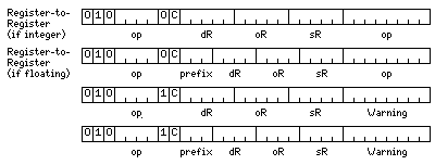
The second group of three-operand register-to-register instructions allows a very large number of possible operations to be specified. So half of this could be reserved to allow a special form for the sixteen most common arithmetic operations which reserves eight bits for another purpose. (All sixteen opcodes can be used as the pointer indirect mode can take its opcodes only from the other half of the available space.)
The assumption is that instructions are fetched 256 bits at a time, which amounts to eight instruction units of 32 bits each. If in one 256-bit block, one of the instructions is of this special form, then the eight warning bits each correspond to one 32-bit unit within the next 256-bit block. A 1 bit indicates that the corresponding 32-bit unit is the first half of a 64-bit instruction.