On the previous page, alternative arrangements of the keys in the main portion of the keyboard, such as the Dvorak layout, were discussed.
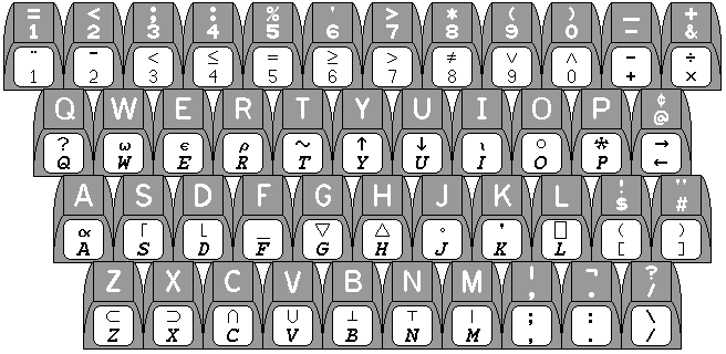
On earlier pages, exotic or specialized keyboards, such as those with mathematical symbols and the Greek alphabet, as used with some of the LISP machines among others, or the specialized keyboard used with APL, were discussed.
Let us look at an elaborate keyboard, such as this one shown on an earlier page:

A keyboard with so many keys would seem to be a specialized device. But it might have a multitude of different specialized uses. How might one indicate that its keys are being used for a particular purpose, depending on the application or operating system in current use?
The diagram below

illustrates how the portions of the keyboard used for function keys both in the original IBM PC keyboard and in the later 101-key keyboard lend themselves to having their purposes described on a cardboard overlay with holes cut in it for the places where the keys are.
Also, for keys other than the primary typing keys, the option exists to use a small, calculator-style, keycap. This creates space between the individual keys, and limiting the height of such keys can ensure that the space is easily visible.
There are keyboards designed for use in playing computer games which are designed to be used with overlays, either for the keyboard as a whole or for a supplementary area with smaller blank keys.

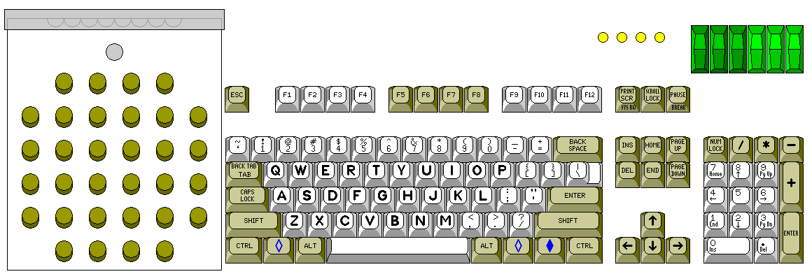
However, so far, no one has yet come out with a keyboard that embodies industry standards in this respect. Illustrated above is a design that uses a keyboard overlay conforming in shape to that used with the IBM 2250 terminal, and which also provides six sense switches and four sense lights, as did the IBM 704 computer, to facilitate full compatibility with the use of the FORTRAN language.
The phrase that comes to mind when discussing keyboard overlays for function keys and the like, however, is "picking the low-hanging fruit". It is also desirable to have the ability to change the legends on the keys in the primary typing area easily. How can this be dealt with?
Since the top of a keycap is usually 1/2 inch wide, while each key has 3/4 inches of space allotted to it, some space between keys could be created without making the part of the key that the fingers touch any smaller; thus, the design of the keycap could be changed to that used with the earliest IBM electric typewriters, or that which was usual with the Flexowriter, where the shape of the key was a square column instead of a tapered pyramid. This, however, would not leave much space between the keys, so the characters on an overlay would not be easily visible unless key travel were limited, and even though the key would not be made smaller, there would be a good chance that it would be criticized as if it were a calculator-key design.
One idea that has recently been tried is to make a soft rubber overlay for the keyboard. If the overlay is not a flat sheet, but has a molded cup for each key, then it is easy enough to press the part of the sheet over each key down when typing on that key.
Another idea that has been around longer, which permits setting up a custom keyboard layout to begin with, although it does not lend itself well to changing that layout periodically, is to make the keycap, or part of the keycap, for each key transparent, so that the key can be opened up, and a cardboard label inserted, and then the protective plastic cover returned.
Keyboard types with short production runs have often been mmanufactured using this principle as well, even if keyboard customization afterwards was not desired as a feature in itself.
The keys on many older manual typewriters were constructed with a metal collar holding down a plastic window over a printed label with the character for the key printed on.
People using APL/360 with the IBM 2741 could affix adhesive stickers to the front of the keys, in the manner shown in this illustration:

and the keyboard of the IBM PC extended the possibilities of attaching stickers to the keys of a keyboard through popularizing an important innovation.
The keycaps on the keyboards of many electric typewriters and nearly all typewriter-like computer keyboards usually have the form of a truncated pyramid, with a square base just short of three-quarters of an inch on a side, with curved, tapering sides that go to a square top that is one-half of an inch on a side.
That square top, however, was not flat; instead, to help guide the fingers, it was concave, its surface having the shape of a portion of the interior surface of a hollow sphere.
With the IBM PC, this was changed. The top surfaces of the keys still had a concavity to guide the fingers, but this time it formed part of the inside of a hollow cylinder. In this way, a label taken from a flat sheet of adhesive plastic could be bent to cover the top face of the key, which it could fit perfectly, because the surface of a cylinder, like that of a cone, is what is known as a developable surface, one that can be bent without stretching to form part of a plane.
Other possibilities exist that have not been tried as often.
A keycap could be designed that consists of a square of transparent material, perhaps supported by a metal frame with legs at the four corners (which then join again to a plate underneath which pushes the central plunger for the keyswitch). Since the keys of a typewriter keyboard are in regular rows, an overlay could slide under those keys to identify them.
Such an overlay would look like a comb, and so, since it consists of multiple thin strips, it would be fragile. As well, this would work best if the keys had limited travel, and the keyboard was not stepped, so that the legend under the key is indeed easily visible through the key.
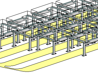
An attempt to illustrate this concept is made in the diagram below:

the yellowish straw-colored cardboard underlay in four strips is being slid from the left under the keycaps.
Another possibility would be to mount keys which were squares of transparent plastic on levers, the way that was done on a manual typewriter, except that the levers are bent as necessary to always pass around, and never under, the keys on rows further up. One could imagine a keyboard of this sort being made from glass instead of plastic, for more transparency, with levers of gleaming stainless steel, being offered by a European designer. The main technical problem would be making keylevers both rigid enough to serve and thin enough so that four or more of them could move freely in the 1/4" space between two keys on the top row. An overlay under such a keyboard could be moved freely so that its legends would be directly behind the appropriate keys in the user's line of sight.
Of course, the ultimate way to relegend a keyboard would be to do it electronically. by allowing each individual key to contain a display. A keyboard of this type, the Optimus Maximus keyboard, is now available from a firm in Russia. In addition to having a display on each key of the conventional keyboard, it has a set of additional programmable keys on the left of the normal keyboard area.
Even such a keyboard does not provide the flexibility required to set up an arbitrary layout.
One could imagine a platform, where keys could be placed horizontally at any position in 3/16" increments, and vertically in positions at 3/8" increments (to allow supporting such keys as a double-height Enter key in their center). Keys whose width is an odd number of units of 3/16" might rest on a keyswitch with contacts shifted over by 3/32" so as to avoid the need to use an increment of 3/32" horizontally, but allow the plunger supporting those keys to be centered.
The vertical distance would actually be slightly more than 3/8" so as to account for the keyboard being sloped; either the bases of the keyswitches would be slanted, or a stair-step construction could be used.
Thus, with a suitable collection of keycaps and keyswitches on such a base, one could arrange the keys to form almost any conventional keyboard layout. Since all keys are at least 3/4" wide, groups of four columns of contacts could be equivalent for scanning purposes.
Copyright (c) 2007, 2009 John J. G. Savard