During World War II, the United States used a rotor machine which was so well designed that it appears to be immune to any kind of cryptanalysis other than a brute force attack, offering security somewhat comparable to that which DES very much later made available in the civilian sector. (Since writing these words, I have noted that, if one had over a dozen messages enciphered at the same initial rotor setting, which would be unlikely in practice, it is possible to compare different alphabets produced by the machine and obtain at least some information about the rotor wirings. From there, the technique used by Frank Rowlett against the M-228 might allow further progress.)
This machine was originally called the ECM Mark II within the predecessor of the NSA that developed it. The ECM Mark I was a machine developed by Edward Hebern, and the ECM Mark III was a machine that, like the Mark II, had irregular rotor movement, but which achieved it by a simpler system. The ECM Mark III is given in one source as a modification of a rotor machine by Edward Hebern, which is reasonable, given that it is largely of mechanical rather than electrical construction, but the modifications that gave it its unique character were, I believe, made within the U. S. Navy without any involvement by Hebern.
The ECM Mark II, our present subject, was developed entirely within the U.S. Government. Its basic principles were originiated within the Army Security Agency, but its the ECM Mark II itself, in its specific form, was developed within the U.S. Navy.
The basic principle of the SIGABA that made it so strong is the use of additional rotors, rather than gears, to control the movement of the rotors used to encrypt a message.
As this excellent design has, very recently, been declassified in its entirety, it has become possible for you and I to examine and admire it.
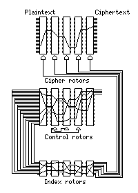
The SIGABA contains fifteen rotors, ten of which are conventional 26-contact rotors, and five of which are smaller rotors with only 10 contacts on each side. These rotors are divided into three groups.
Five 26-contact rotors, called cipher rotors, encipher or decipher the message being transmitted in the same way as the rotors in a regular Hebern rotor machine. Any of them can move after a letter is enciphered; their motion is controlled by electrical signals.
Another five 26-contact rotors are called control rotors. On the input side, the four contacts (corresponding to the letters F, G, H, and I) get electricity. On the output side, the contacts are wired together in nine bunches of various sizes, as follows:
1 B   4 FGH   7 PQRST
2 C   5 IJK   8 UVWXYZ
3 DE  6 LMNO  9 A
These rotors move as if they were controlled by conventional gearing (actually, electromechanical means are also used to move them, for reasons of parts commonality or due to patent considerations): the middle one moves one space for every letter enciphered; the one after it (closer to the output side) moves once for every 26 letters, and the one before the middle rotor moves once for every 676 letters. When a rotor changes from the letter O to the letter N is when a carry takes place to the next slower rotor.
The five 10-contact rotors are called the index rotors. They are only set by hand before starting to use the machine. Nine of their ten inputs are connected to the nine bunches of contacts which take the output of the control rotors, and the numbers of the bunches in the table above show which contact recieves the signal from that bunch. Their ten outputs are connected together in five pairs, each of which supplies the signal which controls the advance of the cipher rotors.
The following diagram illustrates the wiring of the SIGABA:

Because exactly four inputs to the control rotors recieved a live signal, at most four of the cipher rotors could step after any letter was enciphered. Since no signal was ever thrown away, although the number of live signals could be reduced if two were both wired together, at least one of the cipher rotors had to step each time.
When using the machine, the ten 26-contact rotors were first set to their starting positions, which were the ones marked by the letter O instead of the ones marked with the letter A that one might expect, usually with the aid of an automatic feature in the machine. It could also be done by hand, but if the user was not careful, one of the control rotors, particularly one of the two on the outside, could be left in a halfway position, preventing the cipher rotors from ever moving.
The index rotors, however, were set by hand. Setting them was in a sense easier, or at least less problematical, and for each day there were three different settings for them, for three different levels of security classification of the message being sent. The order of the index rotors apparently was at one time changed each day, but during World War II the procedure was changed to always leave these rotors in order.
The wiring of the index rotors (or at least a wiring used at one time with the index rotors) is known, and is as follows:
      Input
      0 1 2 3 4 5 6 7 8 9
Rotor -------------------
  1   7 5 9 1 4 8 2 6 3 0
  2   3 8 1 0 5 9 2 7 6 4
  3   4 0 8 6 1 5 3 2 9 7
  4   3 9 8 0 5 2 6 1 7 4
  5   6 4 9 7 1 3 5 2 8 0
These rotors are all wired by the interval method. In addition, it is always the interval -3 that is duplicated (and therefore the interval +2 that is omitted). And furthermore, the two wires with interval -3 both always start from two contacts which have exactly one contact between them.
This means that they all belong to one class of the classes into which a program I wrote to count the number of interval method wirings for rotors of even size divided the possible wirings into. As it turns out, rotor wirings recorded for the 26-contact rotors of machines Edward Hebern made for the U.S. Navy to test had the same structure, which has led me to suspect that this may also have been true of the 26-contact rotors of the SIGABA, no actual specimens of which (the wirings, not the rotors) have been preserved. However, the actual wirings of two rotors for SIGCUM, a telecipher machine, which were recovered by Frank Rowlett during tests of its security have survived, and have recently been disclosed, and these rotors were not wired according to the interval method. Since SIGCUM was manufactured by the same contractor as SIGABA, and it was also contemporary with the later period of the use of SIGABA, this seems to be more conclusive.
The keyboard on the SIGABA had a row of digits like the keyboard on a regular typewriter. While the SIGABA didn't encipher messages containing digits, the keys for the digits 1 through 5 were used, when the machine was switched to a setup mode, to advance the control rotors. When sending a message, the operator first picked five letters at random, which were sent with the message as an indicator. Then, starting from the OOOOO position, using the 1 to 5 keys, the control rotors were moved to spell out the five letter indicator, starting with the first control rotor (which the 1 key moved). Although the mechanical gears that usually moved the control rotors were not active during this setup mode, each time a number key was pressed, the cipher rotors moved based on the electrical signal travelling through the control and index rotors in the same way as during normal encipherment. Thus, the indicator specified a position for the cipher rotors as well as for the control rotors, but the starting position of the cipher rotors was, in effect, well encrypted.
When messages were enciphered, the space bar could be used on the keyboard, and caused the letter Z to be enciphered; on the other hand, the Z key as well as the X key both caused the letter X to be enciphered. Also, the machine inserted a space after every five letters enciphered for ease of reading for transmission. For decryption, Z printed as space, thus restoring the spaces in the original message.
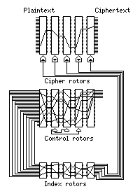
In the postwar period, the CSP-889, as the SIGABA was known in the Navy, was replaced by a modified version, the CSP-2900. This had some interesting differences.
Six, rather than four, inputs to the control rotors were live. These corresponded to the letters D, E, F, G, H, and I. Since this meant that all five cipher rotors could move at the same time, cipher rotors 2 and 4 were changed to move backwards when they moved, so that if all the rotors moved, they still wouldn't all move in step.
The outputs of the control rotors were now gathered in ten bunches instead of nine, and the largest connected together only four contacts, not six. Also, three control rotor outputs were left unused, instead of none, as before. Since the number of discarded outputs was less than six, it was still true that at least one rotor would always move.
The arrangement was:
0 UV   4 FGH    8 WXYZ
1 B    5 IJK    9 A
2 C    6 LMNO
3 DE   7 ST     not connected: PQR
This diagram is modified to illustrate the newer form of the ECM Mark II:
Machines of the ECM Mark II type used for a communications link between the President of the U.S. and the Prime Minister of the U.K., which was called "POTUS-PRIME", were operated in a fashion that produced additional security. The five cipher rotors were set by hand, and apparently so were the control rotors, and the settings for the cipher and control rotors were taken from a list of thirty five-letter groups for use as either of cipher rotor settings and control rotor settings, with a three-letter codeword which was pronounceable and had error-correction properties, for each one. (The two three-letter codewords were combined into a single six-letter group for transmission.) Thus, the idea of increasing the SIGABA key length by using a ten-letter indicator was indeed considered, and it was used, along with the other possible way of achieving ultimate rotor security, a codebook for message indicators, where circumstances warranted the extra effort.
This link was used during World War II, and the British were not allowed access to the American cipher machines at their end at that time.
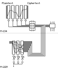
The SIGABA, or the Electric Code Machine Mark II, was developed before World War II by people from both the U.S. Army and the U.S. Navy. The story of its development is a somewhat complicated one. The basic idea of electrically-controlled rotors was originated by W. F. Friedman, who implemented it in the original M-134 machine, which had five rotors that enciphered text, the motion of which was controlled by a paper tape. A plugboard was included to vary which channel of the paper tape controlled which rotor. Frank Rowlett then came up with what could be considered the core concept of the SIGABA: the idea of using rotors to control the rotors that enciphered text.
At the time, the U.S. Army had limited funding for the development of new cipher machines, and thus Friedman and Rowlett embodied this new principle in an add-on device, called the M-229 or SIGGOO, that connected to the M-134. The M-229 had three rotors. A six-position switch controlled how these rotors moved (shown as a plugboard with three plugs and sockets in the diagram). Five inputs to these three rotors, having the role of the control rotors in the SIGABA, were live. The outputs were connected together in two groups of five and three groups of four. Here is a diagram of the combined M-134 and M-229:
Meanwhile, this new idea was conveyed to the cryptological department of the U.S. Navy as well. Laurence F. Safford and Donald J. Seiler developed the Electric Code Machine Mark II (Mark I was the Hebern rotor machine) which was essentially the SIGABA in its final form there. For a period during this development, Army-Navy collaboration was disrupted by other factors, but when channels were reopened, the Army group recognized that the ECM Mark II was a superior embodiment of their ideas, and were happy to accept it as a cipher machine for use by both services.
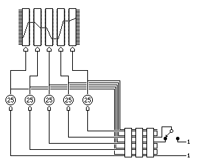
The principle of operation of the ECM Mark III, which achieved irregular rotor motion in a simpler fashion, is illustrated below:
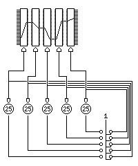
Five pinwheels, each with 25 positions, control the movement of the five rotors. The same output that causes a rotor to move also causes a pinwheel to move.
Although the diagram is in the same format as other diagrams which show electrical wiring, the control of the rotor movement in the ECM Mark III was all-mechanical in nature; the plugboard provided for the connection of tubes constraining a wire, so that the wire could be used to push. The patent refers to this as a Bowden wire; model railroading enthusiasts, who wished to use this principle for remotely controlling the switches on their layouts, at one time sought out Model T Ford replacement parts.
In normal operation, it appears that the plugboard is set up so that four of the five pinwheels are each controlled by another pinwheel. If a pinwheel were controlled by itself, it would simply stop moving as soon as it reached an inactive pin position, so it is unlikely that such a connection could be safely used.
When a pinwheel does not have its input connected, it will move with each letter enciphered. Having at least one pinwheel not connected ensures the pinwheels will not reach a state from which none of them can advance. One could, however, without too great a disaster ensuing, have two pinwheels not connected, using one as the base of a chain of three pinwheels, and the other as the base of a chain of two pinwheels. There might even be advantages in using such an arrangement on infrequent occasions.
As it happens, the number of connection arrangements of each type is 120, or 5!, the same as the number of connections of five inputs to five outputs with no limitations. This prompts one to ask if, in an electrical version of this design, one could somehow adapt rotors similar to the index rotors in a SIGABA to take the place of the plugboard, to simplify the operation of the machine, and indeed one could, by using rotors with five positions, and two contacts at each position, as follows:
The rotors would have to be wired so that both contacts in a pair of contacts on one side would be connected to the corresponding contacts in one of the pairs of contacts on the other side, so that the output and return contacts are permuted identically. (To be completely general, one could use rotational displacements that cancelled out, but that would seem to serve no purpose, except perhaps to befuddle an adversary who captured a machine.)
A patent for the design of the M-134 in which a five channel paper tape controlled whether each of five rotors would step was issued on August 1, 2000, from an application filed on July 25, 1933: U.S. Patent 6,097,812. A previous prototype, the M-134-T1, had a single rotor that could advance to any position each time a letter was enciphered, under the control of a five-channel paper tape. U.S. Patent 2,028,772 was issued for this on January 28, 1936, after filing on January 23, 1932, so this first patent of the series was not kept in secrecy for a long time, unlike the others. Although the design might not have been practical for encryption, the mechanism used to control the rotor might have been used in the construction of jukeboxes. A later patent, U.S. Patent 6,130,946, issued on October 10, 2000, was filed on October 23, 1936, and was for a rotor machine in which each rotor was controlled by a cam of a different size. U.S. Patent 4,143,978, filed on May 4, 1938, and issued on March 13, 1979, with Donald J. Seiler and Bern Anderson as inventors, used five pinwheels, each having 25 positions, to control the rotors, and this is the ECM Mark III.
I had thought that it was quite likely that not only the actual SIGABA or ECM Mark II design was too secret to be the subject of a patent application, but in addition, that it would have been possible that the M-228 and M-229 designs, embodying the unsual and ingenious principle of using rotors to generate multiple bitstreams instead of enciphering a single letter, were treated in the same manner.
However, there was indeed a SIGABA patent, filed for on December 15, 1944, and granted on January 16, 2001, as U.S. Patent 6,175,625.
The source for most of the information on this page is the U.S.S. Pampanito web site, which has an entry in my Links section.
Next
Chapter Start
Skip to Next Section
Table of Contents
Main Page