
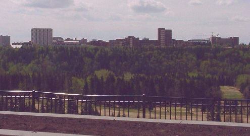
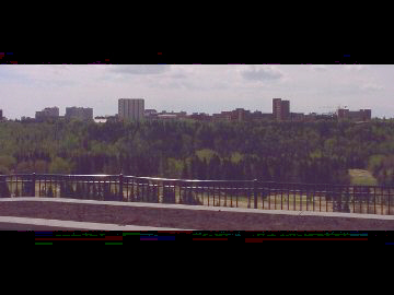
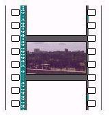
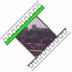
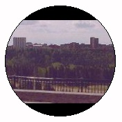
Here is a detail from a photograph I took of the University of Alberta, located here in Edmonton, Alberta. The photograph was taken from a park across the North Saskatchewan River from it.
This picture happens to have a ratio of width to height of 64:27, which can also be expressed approximately as 2.37:1.
When you are watching a "spectacular" movie in the theatre, it is likely that you are watching a movie with the aspect ratio of 2.35:1, which is close to what this picture represents.
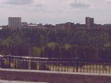
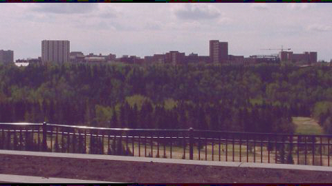
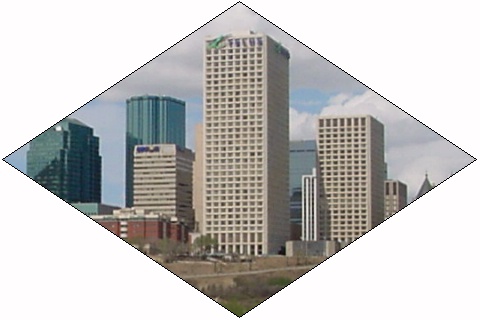
Working from the same source picture, here is an image with a ratio of width to height of 11:6, approximately 1.83:1.
This comes close to the 1.85:1 aspect ratio that is the usual aspect ratio used in North America for movies.

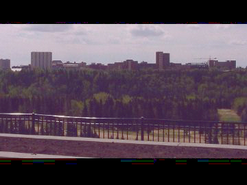
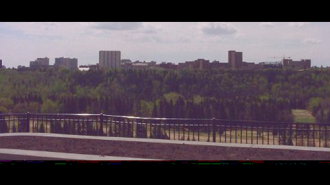
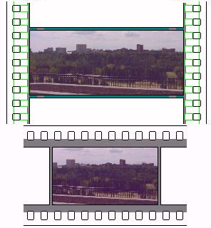
Again working from the same source picture, here is an image with a ratio of width to height of 16:9, approximately 1.77:1. This is the aspect ratio used for widescreen television and HDTV.
DVD players are designed to play movies consisting of either 4:3 images or 16:9 images, with the same pixels, changed somewhat in shape, representing either type of image. Movies having other aspect ratios lose some of the available pixels to the "black bars" you see on the screen, but fewer pixels are devoted to encoding the black bars when the DVD contains 16:9 images; such DVDs are called "anamorphic" or "enhanced for widescreen". If you have a regular 4:3 TV set, though, your DVD player has to convert the 480 scan lines of the image on the DVD to appear within only 360 scan lines on your TV set, so this may actually compromise picture quality slightly.
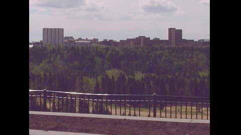
Now, here is another image, this time composed for the regular aspect ratio of ordinary TV sets, with a ratio of width to height of 4:3, the Edison silent film aspect ratio of 1.33:1.

If you want to compare the resolutions offered by regular TV and by HDTV, though, instead of looking at a 4:3 picture of the same size, one has to compare two pictures like this (in both cases, the resolution, in both directions, is only 1/4 that of the actual television format represented):
Regular TV:
HDTV:
Enlarging a segment of the first image to match the corresponding segment of the second, one obtains this image:
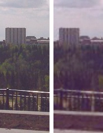
which, while simulated, gives an idea of the improvement in resolution. Because what is seen in this picture is only one quarter of the height of the screen, of course, regular television doesn't look as blurry as the comparison picture representing it does.
HDTV will be wonderful when it arrives, providing a movie-like experience when watching television. However, not everyone is really all that interested in going out and spending lots of money on a new TV set, let alone one that would be very expensive. As well, HDTV is controversial for two other reasons; there is the issue in the U.S. of how bandwidth was allocated for it, and many people are unhappy about how arrangements are being made to ensure that there won't be VCRs for HDTV quite like the ones available for regular TV.
In the images above, we have seen what the proportions of various common film presentation types look like. Both of the ratios currently used for movies are wider than those used for either regular or widescreen television. So the dreaded "black bars" cannot be avoided if one wishes to see the whole movie as it appeared in the theatre. The extent of this phenomenon will be illustrated by the images below.
When a movie in the 1.85:1 aspect ratio is presented in its original form on your regular TV set, it looks like this:
When the movie is instead in the 2.35:1 aspect ratio associated with the more lavishly spectacular features, it looks like this:
Of course, there are many other aspect ratios, but these two are the most common. Instead of 2.35:1, some spectacular widescreen movies were made in 2.55:1 and even 2.76:1. Instead of 1.85:1, other countries have used more modest enhancements of the original 1.33 aspect ratios for their theatres, both the 1.77:1 ratio used for HDTV, and the even more modest 1.66:1 used in much of Europe.
With one of the fancy new widescreen TV sets, although even a 1.85:1 movie is still wider than the screen, now the "black bars" are quite narrow indeed:
And even for the spectacular 2.35:1 movies, things are not nearly so bad as on a regular television:
But, on the other hand, there is a downside. Regular, old-fashioned TV shows will now look like this:
In any case, the film buffs who enjoy seeing movies in their authentic theatrical form on DVD want YOU to run out and buy a widescreen TV set if you're planning to get a DVD player, so that you don't do anything foolish, like encouraging studios to present their films on DVD in a form "modified to fit your screen" as is already done on broadcast television and on VHS. They would like to have a premium medium where nearly all movies that are available are available in their original form.
But before you decide that this is terribly selfish of them, it should be noted that many movies are substantially altered for the worse when they are so modified.
Incidentally, it is no accident that the black bars are quite narrow for the common 1.85:1 aspect ratio, when viewed on a 16:9 monitor. The original recommendation to the SMPTE for that ratio, by Dr. Kerns H. Powers, made on May 4, 1984, was based on an analysis of the different aspect ratios in film, which led to him proposing this ratio as an ideal compromise.
The fact that 16:9 is 4 squared to 3 squared also means that a television with this aspect ratio could either display nine thumbnails, in a 3 by 3 array, of programs on different channels in the 16:9 ratio, or twelve thumbnails, in a 4 by 3 array, of programs on different channels in the 4:3 ratio. Or a 16:9 monitor could show inputs from twelve cameras in the 4:3 aspect ratio in a security system.
The SONY HDM-3830 widescreen monitor had a 16:9 aspect ratio; its existence and availability may also have influenced the decision in Japan to change the aspect ratio of the HiVision analog HDTV system from the 2:1 value initially considered to the 16:9 value actually adopted. However, that monitor may date from 1985, subsequent to Dr. Powers' recommendation.
Movies in the 2.35:1 aspect ratio are converted to 1.33:1 by the method one normally expects, selecting the most important part of the scene horizontally at any given time to fit into the narrower screen. This is also done for parts of movies in the 1.85:1 format. This method is called "Pan and Scan".
However, it is a little known fact that movies in the 1.85:1 format are usually shot on regular 1.33:1 film, and so when a conversion is performed, often most of the movie will be converted by showing the whole original 1.33:1 image photographed. This is referred to as "open matte".
With Pan and Scan, you are losing part of the picture, so that the part you retain can be bigger on your TV set.
With open matte, you are seeing additional picture information, omitted to let the movie fit into the theatre's wide screen.
Thus, these two techniques are complementary. But what remains the same, for most movies, is that they were filmed with their appearance in the theatre in mind. So, the part of the picture that is lost in Pan and Scan is likely to be important, while what is gained with open matte is likely to negatively affect the composition of the scene, and may even include the odd overhead boom microphone.
Of course, on any display device, every pixel costs money. Thus, the "black bars" that result when the aspect ratio of the content does not match that of the display device are irritating to many people.
At the present time, it is not practical to make a flat-panel display device without a border around it. If it were possible to do so, based on the fact that the square root of 1 1/3 is approximately 1 1/6, a technical solution to the "black bar" problem is possible that does not require a screen made of pixels that flow like liquid.
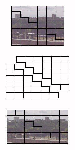
Instead, the screen only needs to be divided into two pieces, with a stepped shape, so that the pieces can be fitted together yielding a shape 6 units wide by 7 units high, or 7 units wide by 6 units high. In the illustration above, the unit rectangle is chosen to have an aspect ratio of 14:9, yielding an exact match to the 4:3 aspect ratio, and very slight black bars on the sides, rather than on the top and bottom, for the 16:9 aspect ratio.
An aspect ratio of 32:21 would yield an exact match for the 16:9 aspect ratio instead, and again, since 7/6 squared is slightly greater than 4:3, which is not only the standard aspect ratio, but also the ratio between the two aspect ratios, the black bars appear in the opposite place to the expected if the two programs shared the same screen: on the top and bottom for the less wide 4:3 ratio.
Instead of going from 6:7 to 7:6, of course, one could go from 7:8 to 8:7 and undercorrect instead of overcorrecting for the difference in aspect ratios. Or, one could further increase the amount by which the aspect ratio is altered, and shift the screen from the 4:3 aspect ratio to one approximating the 2.35:1 aspect ratio; this could be done by going from 3:4 to 4:3, leading to the 64:27 aspect ratio shown above as an approximation to 2.35:1, as illustrated below:
Note that the individual cells used in this scheme of stepping happen to have the current standard 16:9 aspect ratio; this illustrates that this ratio is the geometric mean of 4:3 and 64:27, placing it, in a sense, almost halfway between old-fashioned movies and TV on the one side, and panoramic widescreen at 2.35:1 at the other. This was, of course, one of the arguments used for the adoption of 16:9 as a standard.
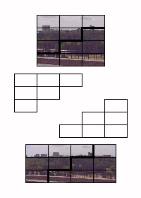
Beyond that, one could go from 2:3 to 3:2, leading to a 3:1 aspect ratio, or go from 1:2 to 2:1, that is, divide the 4:3 screen into two rectangles, each having an 8:3 aspect ratio, and move them from one above the other, giving 4:3, to moving them to be side-by-side, giving 16:3, or a screen 5 1/3 times as wide as it is high. This last possibility suggests dividing the screen into three pieces instead of two for still more width, and the same can be done using the stepped principle:
AAA
BAA   CBAAA
CBA   CCBAA
CCB   CCCBA
CCC
thus achieving ratio changes whose parts differ by two. However, the middle segment consists of rectangles only joined by their corners; this is not a real problem, as they can be joined by a rear layer. This could allow going from 13:15 to 15:13, for a closer approximation to 16:9 from 4:3, but it does not seem that the additional effort would be worth it.
With this 14:9 ratio in each rectangle, and given a vertical resolution of 1080 scan lines for the HDTV aspect-ratio image, each of the 42 smaller rectangles of which the image is made would contain 280 by 180 pixels; so, in the 4:3 format, the resolution would be 1680 by 1260 pixels, and in 16:9 format, the screen would contain 1960 by 1080 pixels, of which 1920 by 1080 pixels would be actually used, leaving the "black bars" on either side only 20 pixels wide each.
Since images displayed in 4:3 format would usually have a vertical resolution of 480 lines, a modest black border so that the height of the area used was 1200 pixels instead of 1260 pixels would make the ratio of resolutions a simple 2:5 ratio, presumably simplifying conversion calculations.
The result of that would be a border like that shown in blue in the modified diagram below:
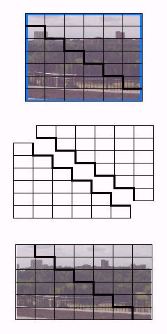
still quite modest compared to the "black bars" on today's fixed aspect ratio displays.
Note also that this scheme is not totally impractical even with present technology. A projection television could be made which projected the lower stepped area with one fixed lens, and which used a lens to project the other stepped area that was movable, so that this area could be placed in either of the two required positions in relation to the first area. This would solve the problem of having a border around the image-generating element.
It would require accurate alignment of the two areas being projected, of course. Also, with a projection display, the problem of display area being "wasted" is far less visible and obtrusive.
This diagram illustrates a few 35mm motion picture film formats, those which were most influential in bringing about the most common movie film formats in use today.
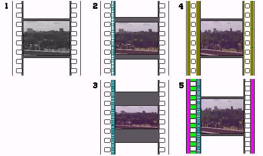
The first format, indicated by (1) in the diagram, is what started it all, 35mm silent film, as originated by Edison. This was originally projected at 16 frames a second, although silent home movies later were changed to 18 frames per second. The image had the same shape as that of a television screen, 4 units wide by 3 units high, or a 1.33:1 aspect ratio.
The second format, indicated by (2) in the diagram, shows what happened when sound was introduced. Now, 24 frames were shown per second. Since it was necessary to make room for an optical sound track, the picture was reduced in size horizontally; to keep the same shape, it also had to be reduced in size vertically. The aspect ratio was actually made very slightly wider by this, giving an aspect ratio of 1.37:1. This shape is known as the Academy Aperture.
The third format, indicated by (3) in the diagram, indicates the method used for widescreen movies of moderate extension. The picture is just cropped vertically some more. In the diagram, the common North American aspect ratio of 1.85:1 is illustrated. 1.66:1, popular in Europe, and 1.77:1, also used in film, as well as being the 16:9 HDTV aspect ratio, can be achieved the same way, through less severe cropping. The soundtrack is now shown as being in two bands, for stereo sound. The rectangles showing the frames of the movie are shown as having the desired aspect ratio: this is true of film that is "hard matted". It is more common for film to be "soft matted"; that is, the picture on the film is as tall as with silent film, but a mask in the projector is used to obtain the desired aspect ratio. The film is shown this way so that the area of the film that really contains the movie intended to be seen is clearly visible.
The fourth format, indicated by (4) in the diagram, is CinemaScope. Here, vertical cropping is avoided. The image on the film, therefore, is less wide than a 1.33:1 image, but it is expanded by an anamorphic lens to produce an image with a 2.35:1 aspect ratio on the screen. Note that the perforations have been made smaller, to make room for extra sound tracks. The sound tracks are recorded magnetically, and, in order, from left to right in the diagram, they are the left channel, the center channel, the rear channel, and the right channel. The rear channel is recorded on the narrower band, since it is bandlimited, being used for the "surround sound" track.
The fifth illustration, (5), shows how a modern anamorphic film now appears. The picture on the film is very slightly wider, giving an aspect ratio of 2.39:1 when projected. It is now centered at the same point as a 1.85:1 movie (before, the offsets were slightly different, the one for CinemaScope being smaller). In addition to a stereo sound track, once again optical (now using Dolby noise reduction and matrixing) the purple areas show where the Sony SDDS digital audio is placed, and the light green areas show where Dolby Digital audio is placed. Not shown, due to the small scale, is a timing track, on the edge of the optical sound track area closest to the pictures, used to synchronize the movie with DTS audio supplied to theaters on special Compact Discs. This same complement of audio options is, of course, used with modern 1.85:1 films as well.
The format shown in (3) is somewhat wasteful of film stock. A more efficient way of filming widescreen movies without an anamorphic lens was developed during the 1970s and 1980s, called "3-perf", wherein the 35mm film is advanced by three sprockets instead of four for each frame, as illustrated in the diagram below:
Incidentally, I remember having heard of a film format, using 16 millimetre film stock, that operated on the same principle as Paramount's VistaVision. The idea was to permit movies to be shot using cameras that were compact, and easy to handle for independent film-makers, that would still have a high enough resolution to be transferred to 35 mm motion picture film for theatrical distribution.
Unfortunately, I haven't been able to locate any references to this to confirm my recollection.
The diagram above illustrates how this could have worked. If normal 16mm film with a magnetic sound stripe is used as the basis, then using two frames horizontally would produce a reasonable aspect ratio. If, however, sound on the film was foregone, and Super 16 was used as the basis, then it would take three frames to produce a frame with a reasonable aspect ratio when running the film horizontally.
How does an anamorphic lens, used for placing the squeezed version of a 2.35:1 image on film, work?
The basic idea is that a convex and concave cylindrical lens, as illustrated in the upper left corner of the diagram above, will create a kind of Galilean telescope that magnifies in one direction only, the direction along which the lenses are curved. In the perpendicular direction, they are flat, and act like flat pieces of glass.
Thus, cylinder lenses can be considered, in an optical design, to be lenses that can be considered to be either present or absent, from the viewpoint of two planes intersecting the optical axis at right angles. Thus, the diagram along the bottom of the page shows how an anamorphic attachment for a projection lens would work, consisting of the two lenses shown as red outlines.
For a camera lens, though, the situation is more complex, because focusing on objects at different distances can result in the magnification of the anamorphic section of the lens changing, and thus anamorphic camera lenses are considerably more expensive than anamorphic projection lenses.
Today, improved film stocks make 35mm film sharper than ever before, and there is a trend towards making films using HDTV equipment. While the HDTV resolution of 1920 by 1080 is lower than that of 35mm film, the absence of grain, which produces noise on 35mm film at a scale larger than the size of an HDTV pixel already makes HDTV-style video comparable to film in the opinion of many.
As any photographer knows, faster films have coarser grain, and slow films, which require lots of light or long exposure times to take pictures, can have extremely high resolution and fine and unobtrusive grain. Thus, a film can be shot using a fast film in a large format, and then release prints can be manufactured on a slow and high-resolution film stock. Thus, audiences can benefit from sharper, clearer pictures when watching a 35mm print of a movie shot using a larger film format.
Of course, it is still even better to watch the movie on a large format print.
Two important large formats for movie-making are illustrated below:
The top part of the illustration shows what 70mm and 65mm film look like. The border of 70mm film is shown in black, that of 65mm film in light green. When movies are made, the sound is not recorded right on the film, as is done when making Super 8 home movies with sound. Instead, the sound is applied to the film during the editing process. This is why the famous "clapper board" is used to begin the shooting of a scene in a movie: the sound it makes can be synchronized with the image of the bar at the top hitting the blackboard below with the identification of the scene.
Thus, movies to be exhibited in 70mm format are shot on 65mm format; the picture is the same size on the film, but the extra 5mm, used for the soundtracks on the release print, is not required. Film formats of this type include Todd-AO and Super Panavision 70. Note that the image on the film is only slightly larger vertically than a standard 35mm image, with the film advanced by five perforations instead of four for each frame. A 2.35:1 image is used in the illustration; more of the available area on the film could be used with a somewhat less wide aspect ratio, and that used for the original Todd-AO films was 2.21:1, the one ideally suited to this format.
The bottom part of the illustration shows how standard 35mm film can also be used to take larger images. Here, the film is run sideways, so that the short dimension of the image instead of the long one is constrained by the width of the film stock. This illustrates the VistaVision format, developed by Paramount, and used by it during most of the 'fifties, in which the film is advanced eight perforations horizontally for each frame. It was primarily used as a source format for the making of high-quality 35mm prints, although a very few movies were released in that format as well. The illustration shows an image in the 1.85:1 aspect ratio, which leaves room for soundtracks on the film, as required for release prints. Some of the films made in VistaVision were in this aspect ratio; others were in 1.66:1, which again uses more of the available area of the film.
35mm film, running sideways, at 8 perforations per frame, was also used for the Technirama format; since the available film area was more suited to an aspect ratio such as 1.66:1, this format provided an aspect ratio of 2.35:1 by using an anamorphic lens to stretch the image by a factor of 1.5, converting an image on the film with an aspect ratio of 1.5667:1 to one on the screen of 2.35:1.
Incidentally, it might be noted, as can be seen from the illustration, that if ten rather than eight perforations were used, an image in the 2.35:1 aspect ratio could be put on the film at a size almost identical to that available using 65mm film.
The more recent IMAX format uses 70mm film and places a larger picture on the film by turning it sideways as well, although its aspect ratio is close to 4:3, making the potential gain in size smaller. As far as I know, nobody has turned 16mm sideways to produce an improved format for use by filmmakers with restricted budgets, and given today's advances in video, it is unlikely that anyone will bother now: while HDTV cameras are expensive at the moment, there seems to be no technical reason why even consumer camcorders would not offer the 1920 by 1080 resolution in the near future.
But here are the formats that were used with 16mm film:
On the left, we see conventional 16mm film. Originally, it had sprockets on both sides of the film; omitting the second set of sprockets allowed a continues optical soundtrack, as shown in green in the illustration.
In the center, we see the Super 16 format. With this format, the extra space made available by removing the sprockets on one side is used for a larger picture, which also has a wider aspect ratio, and sound has to be recorded externally. Usually, material filmed in this manner is converted to 35mm prints with a 1.66:1 aspect ratio.
On the right, we see the Ultra 16 format. Since the image is centered on the film, it is easier to adapt a standard 16mm camera to handle this format (for example, the area of coverage of the lenses is not a problem). This format wastes space between the frames, so unlike Super 16, it doesn't maximize the use of the available film, but it is attractive because it allows a wider 1.85:1 aspect ratio, which, as noted above, is the one most commonly used with current theatrical features. Although some empty space is left on the sides of the film, it isn't enough for a soundtrack, and so this format would work just as well with the second set of sprockets left on the other side of the film. And thus it is shown that way in the diagram, although in practise, double-sprocket film would have been obsolete when Ultra 16 was used.
For the sake of completeness, since a number of film formats have been illustrated on this page,
here is an illustration of film formats used, or in one case, merely proposed, for home movies; first, 9.5 millimetre film, originally devised in France, and then the well-known 8 mm film formats, first the original one, and then the new Super 8 format, intended to address the issue of the small image size of the original. And finaly an improvement to the 8mm format said to have been developed by one M. Garcin in 1945, according to a French book cited in a 1965 issue of Popular Photography.
Of course, the image size with 9.5 mm film was still much greater; but the 8mm formats are more conservatively designed, with the sprockets to one side so that an accident in the projector is less likely to damage the actual images (and so the damage could more completely be repared with perforated splicing tape).
Even the double-sprocket Garcin proposal does not equal the frame size of 9.5 mm film, and its frame size seems to me to be only a little larger than that of normal Super 8 film. Of course, one could start with Super 8, and use three frames to make one horizontal frame; then something comparable to 9.5 mm could be achieved.
Quite some time ago, I was reading an old book on the history of film. In it, the author noted that the (then) recent trend towards wider and wider screen formats was not in the best interests of the medium, as it forced every shot to emphasize the horizontal.
While there have been experiments with screens that varied in size during a film, I had thought of a simpler idea which could address the issue. When I thought of it originally, I visualized something requiring two sets of anamorphic lenses, but that is not necessary.
Combining the space required for a soundrack with going from four perforations to five, it is easy to make the image on the film an exact square. This lets one run the film through the projector at an angle of 45 degrees to the vertical. Then, an anamorphic lens can expand the image by a modest factor, perhaps so as to give a diamond-shaped image on the screen with an aspect ratio of 1.5:1. With a screen of this shape, a scene emphasizing the horizontal can stretch from the left corner to the right corner, while a scene emphasizing the vertical can stretch from the top corner to the bottom corner.
Thus, one can frame a tall building in the center of an image, and still allow a sense of the panoramic skyline of which it forms a part; it might, for example, be suited to a movie about a giant ape climbing the Empire State Building.
Considerably more information on this fascinating topic is available at the widescreen museum, and another page of interest is this widescreen advocacy page, as well as this Swedish page.
Speaking of "black bars" in television pictures, of course, at one time, in the very early days of television - and once again in the case of some of the earliest color TV sets to become available - one saw black bars on one's TV sets even when watching programs in the conventional 4:3 aspect ratio.
Yes, back in the days when they made round picture tubes, because making picture tubes that were rectangular in shape was too complicated. And, when the color TV set emerged, the geometry of the shadow mask for the front surface of a rectangular picture tube was too complicated at first as well.
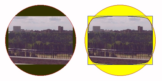
The following diagram
illustrates three possible choices for the size of a rectangular image in the 4:3 aspect ratio when viewed on a picture tube with a circular display area. The first shows the entire rectangular picture area, with a black border around the picture except where its corners touch the circumference of the circular display. The second is the most common compromise, the size at which as much as possible of the picture is displayed while only having black bars at the top and bottom; some of the early color TV sets with circular picture tubes had a frame in front of the picture tube designed for this setting. The third shows the picture enlarged so that its height matches the diameter of the picture tube, so that black bars are completely avoided, at the cost of not being able to see a considerable amount of the right and left sides of the picture.
As there were owners of round-tube TV sets that did adjust them in the third way illustrated, and adjustment in the second manner was far more common than adjustment in the first, we have precedent which allows us to be aware that an antipathy towards "black bars", or unused display area, is common.
The first of the three possibilities illustrates why rectangular picture tubes were originally advertised by their diagonal measurements, rather than by, say, their widths, as a naïve consumer might think more appropriate; it was so that the comparison between rectangular and round picture tubes would be fair. This was eventually changed so that television sets would be, instead, advertised by their display area.
The second of the two configurations shown in the diagram above does cut off somewhat more of the picture than a conventional rectangular-tube television set, but those more modern TV sets did not show the entire picture without any overscan either, as illustrated in the first of those configurations. Thus, if what we wanted to achieve was only to display everything that could be seen on a conventional rectangular-tube television, but not the entire transmitted image, we would only need to go to a configuration intermediate between the first two possibilities shown above, as the diagram below illustrates:
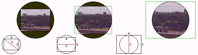
One convenient characteristic of the 4:3 aspect ratio introduced with 35mm film as set forth by Thomas Edison is that the diagonal is in a simple integer ratio to the sides, given the 3-4-5 Pythagorean triangle.

Pythagorean triples exist that approach the widescreen aspect ratios in common use as well. Thus, the 16:9 ratio, for a 1.77778:1 aspect ratio, can be approximated by the 15:8 ratio, making use of the 8-15-17 Pythagorean triangle, for a 1.875:1 aspect ratio; and the 2.35:1 aspect ratio can be approximated by a 12:5 ratio, giving a 2.4:1 aspect ratio, making use of the 5-12-13 Pythagorean triangle.
Copyright (c) 2001, 2006, 2021 John J. G. Savard