The current HDTV standards, which call for a 1080-line picture with a 16:9 aspect ratio were preceded by an analogue television standard, originally used in Japan, which was an 1125-line system also using the 16:9 ratio. This did not involve a decrease in the resolution of the picture; the image presented to the viewer in that analogue system was made up of 1035 lines, but when the lines used for synchronization and retrace were counted, the total was 1125 lines.
This was the Japanese MUSE system (Multiple Sub-Nyquist Sampling Encoding), which was transmitted by satellite, using a sophisticated analog compression strategy to allow the signal to fit in a channel only 8.1 megahertz wide. JVC even developed analog VCRs for this system for home use, following a standard called W-VHS.
The tape cassettes for this format used special metal-particle tape in order to be able to record at a higher frequency. The recording drum had eleven recording heads (and one dummy head for balance). The cassettes were physically compatible with normal VHS cassettes. A demo tape that JVC shipped with W-VHS equipment showed, at HDTV resolution, scenic wonders of the United States, and was titled Great America. As recording analog HDTV-quality video was difficult and expensive, compared to how easily we can store high-resolution digital video today, I can't really, despite the temptation, joke that bringing back W-VHS would be a way to make America great again that everyone could agree on.
Similarly, only 480 lines of a picture in the 525-line NTSC system are considered useful. (From current DVD standards: the actual television standard defines 486 (or 485? or 483?) lines as visible, and, originally, the lines used for closed captioning, and for providing a color burst signal combined with different brightness levels - a way of achieving, but with NTSC compatibility, correction for the phase shift problem that led to PAL and SECAM - were also visible. Similarly, but in the opposite direction, in the Japanese MUSE system, of the 1125 lines broadcast, 1035, rather than 1080, were visible.)
Some, but not all, television systems used a total number of lines that was the product of small odd primes, so as to facilitate deriving the vertical scanning frequency from the horizontal scanning frequency:
 405   3 * 3 * 3 * 3 * 5    British black-and-white standard (50 Hz), CBS field-sequential color (144 Hz)
 441   3 * 3 * 7 * 7        American pre-war "experimental" broadcasting (30 Hz, non-interlaced)
 525   3 * 5 * 5 * 7        American 60 Hz standard
 625   5 * 5 * 5 * 5        European 50 Hz color standard
 819   3 * 3 * 7 * 13       French black-and-white standard (50 Hz)
1125   3 * 3 * 5 * 5 * 5    Japanese analog HDTV standard (60 Hz)
In the CBS color system, conventional interlacing, with alternate fields having odd and even scan lines, was used; in addition, the fields alternated between red, green, and blue, and thus, over six fields, every scan line, both odd and even, was presented in each of the three colors. 144 divided by 6 is 24, the frame rate of motion-picture film.
In the British 405-line system, 377 lines were visible; in the French 819-line system, 768 lines were visible. My source for this, though, identifies the 525-line NTSC system as having 480 visible lines; that's what it is often considered as nominally being these days, and how DVD players treat it, but television transmission standards gave it more. As for 625-line television, it is said to have 576 visible lines.
Recently, I have learned that there is a connection between this and the choice of the 44,100 sample per second rate used for CD audio. The digital data used for the Compact Disc was recorded on video tape recorders which were slightly modified, and to which analog to digital conversion circuitry for the audio being recorded was added.
525 lines per frame at 30 frames per second is 15,750 lines per second, and 625 lines per frame at 25 frames per second is 15,625 lines per second, so the number of scan lines available for both television systems was very similar in each case.
The NTSC version of a recorder for CD audio used 490 of the 525 scan lines in a frame, rather than just 480, to record data; 490 times 30 is 14,700, which is one third of 44,100, so if six 16-bit samples are placed on each line of video, a 44.1 kHz stereo audio sample stream can be placed on tape.
And 490 is a multiple of 5, so if you take out the 5 and put in a 6, you get the number of lines needed per frame on a PAL or SECAM video tape recorder - 588 lines, again, slightly over the 576 visible lines for normal television given above.
Presumably, there was no problem in using this number of lines per frame for digital data (for one thing, it wouldn't matter if the blanking portion of the video signal was used, as the signal encoding sound was not intended for display on the CRT of a television set, so only interference with the actual vertical sync signal, including the equalizing pulses, would matter), and, of course, it was desirable to have the audio sampling rate as high as could reasonably be attained to simplify the design of the low-pass filters used to prevent aliasing when sound sources were digitally sampled.
I had thought that it would be a good idea, if an analogue HDTV system were to be used, to conserve bandwith by displaying 24 frames per second instead of 30 frames per second, to correspond with the frame rate of motion picture film. To achieve this, and yet also avoid a clash with the 60 Hz frequency of electrical power, I had thought in terms of using a field rate of 120 Hz, with quintuple interlacing. (Of course, it might be that 120 Hz, rather than being almost as good as 60 Hz, might even be the worst possible frequency to use for the picture distortion that 60 Hz protects against, but I suspect that this need not happen until one reaches 240 Hz.)
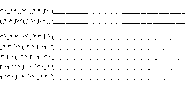
The first two lines in this diagram show what equalization pulses look like with conventional interlacing:

the horizontal sync pulses are reduced to half their width, and come twice as often, so that these smaller pulses do not vary in their relationship to the vertical sync pulse (which is itself broken by going from the sync level to the mere blanking level for a time of equal duration, just before when a horizontal sync pulse would start); the bottom five lines show how the same principle would have to be applied to quintuple interlacing, with the horizontal sync pulses coming five times as often, and reduced to one-fifth of their width. (There is still a short pulse up followed by a short pulse down at the end of the vertical sync pulse for quintuple interlacing, but the scale of the diagram prevents it from being visible.)
At the time, I had thought of simply going from 262.5 lines per field to 262.4 lines per field. But considering the need to go to a number of lines that is a product of small odd primes, one might go to 264.6 lines to get a 1323-line picture (3 * 3 * 3 * 7 * 7), or, to get closer to 1125 lines, 217.8 lines for a 1089-line (3 * 3 * 11 * 11) standard, but that only allows 9 scan lines for vertical retrace and blanking, and those 9 have to be divided by 5 to give what is available for each field, so the vertical resolution would have to be decreased, instead. Because quintuple interlace means that 5 cannot be used as one of the small primes, the number of choices is reduced; but, on the other hand there is no reason why 2 could not be used when an odd number of fields is used to make a frame, since producing a second harmonic from a sine wave is as simple as rectifying it.
Thus, 237.6 lines gives an 1188-line (2 * 2 * 3 * 3 * 3 * 11) picture, which is a more reasonable choice.
Also, if one was not thinking of HDTV, but simply an alternative to the conventional television standard, 587 lines per frame, and 117 2/5 lines per field, would allocate the additional resolution gained from going from 30 frames per second to 24 frames per second equally to the vertical and the horizontal. But 587 is a prime number. However, alternative numbers close at hand are 582, 583, 588, 592, and 593.
582 = 2 * 3 * 97
583 = 11 * 53
587 = 587
588 = 2 * 2 * 2 * 3 * 7 * 7
592 = 2 * 2 * 2 * 2 * 37
593 = 593
So 588 lines per frame with 117 3/5 lines per field would have been a possible choice.
Thus, one could go with an 1176-line standard, 2 * 2 * 2 * 3 * 7 * 7, for for 235.2 lines per field, or an 1152-line standard, 2 * 2 * 2 * 2 * 2 * 2 * 2 * 3 * 3, for 230.4 lines per field, and the latter is preferable, since an odd .4 lines per field, rather than an odd .2 lines per field, would produce a better-appearing interlace, as it would approximate double interlace with 48 frames a second.
Incidentally, while 1089 is 3 * 3 * 11 * 11, 1088 is 2 * 2 * 2 * 2 * 2 * 2 * 17, allowing 217.6 lines per field; again, that would require a reduction in resolution to be workable, although today digital image buffering could remove the need for a long vertical blanking interval. Also, one could transmit 1035 visible lines instead of 1080 visible lines... but if 1125 scan lines sufficed for transmitting 1035 lines of picture, then 1152 scan lines are not wasteful for transmitting 1080 lines of picture.
One problem that might prevent the adoption of such a standard as described here is simply that 1152 might be thought of as a misprint for 1125!
The principle behind quintuple interlace is illustrated in the image below, divided into five vertical strips representing the five successive fields which make up a frame:
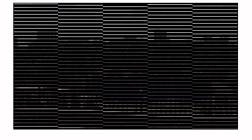
With 230.4 lines per field, instead of the scan lines slowly crawling down the picture, they would more closely approximate alternation between odd and even scan lines as produced by conventional interlace, but with a little difference that leads to five, rather than two, different vertical positions of the raster for each field, thus yielding the additional vertical detail. Since the number of lines per field, at 230.4, is of the same order of magnitude as the 262.5 of conventional television, the proportion of the signal devoted to vertical sync need not be significantly changed.
Note that while this is simply a different way to present movie films shot at 24fps, and is intended to be similar, although slightly superior, in quality to a 1080i display, that is, 1080i60, (a 1080p display, that is, 1080p60, would be refreshed twice as often) and, with proper conversion, any 1080-line presentation of film is simply a presentation of the information in a 1080p24 source in essence, for live television, or material shot on videotape, this is a novel form of presentation, since then the time at which each scan line is presented is of the essence, and it presents 120 fps motion over the entire screen, although at a greatly reduced vertical resolution, and so one would require a new standard for storing video of this kind; it could be called 1080q120.
Conversion from 1080i60 to 1080q120 could proceed as follows: first, take the 1080i60 video two fields, or one frame, at a time, and assume it can be converted to 1080p30 without averaging video from successive frames, and then directly convert to 1080q120, without using 1080p24 as an intermediate step, by taking each 1080p30 frame, and displaying only 4/5ths of the scan lines from that frame in the 1080q120 signal, the omitted group of scan lines changing with each frame.
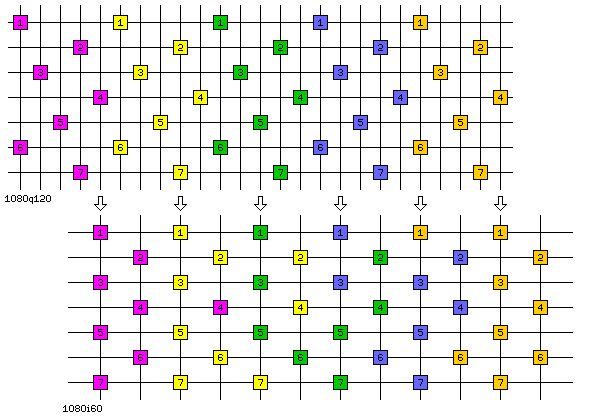
Conversion from 1080q120 source material to 1080i60, on the other hand, could use 1080p24 as the first intermediate step, and then the usual 3:2 pulldown for presentation of film material would be applied, so that half the frames of 1080p24 would be presented in two successive fields of 180i60, and the other half would be presented in three fields, one of them a duplicate. Another way to perform the conversion would be to use 1080p30 as the first intermediate step, taking the most recent scan lines available at a given time to form the frames; this scheme is illustrated in the diagram below:
One could go further, and have no intermediate steps, and just display the most recent scan lines available for each field of the final 1080i60 result; this would lead to a pattern of choices that only repeated every 10 lines instead of every 5, so it would not be the same scheme of conversion with a time offset, as one might initially suspect.
In the MPEG-2 standard, the compression of interleaved video is handled as follows: the even and the odd fields are compressed independently, as if they were completely independent streams of pictures having half the vertical extent. Some thought will be sufficient to realize that this should not materially affect the compression ratio of the scheme. Even so, it would seem that such a scheme would lead to aliasing, and that it would also be suboptimal in compression, due to ignoring the similarities between the two streams.
And, of course, any problems this technique might have would be exacerbated with quintuple interlace. However, there are two mitigating factors. One is that the only time either 1080i60 or 1080q120 would be used is for live or videotaped material, which is both less common, and which tends to be less critical for picture quality than material derived from film. The other is that this technique has one very significant virtue that potential alternatives lack: it avoids contributing to a particularly distracting form of artifact, where events leave ghosts behind them, or are anticipated. Of course, there is some danger of that with motion compression as well, but attempting to deal with interlacing in an elaborate manner seems likely to make the problem either significantly more acute or at least harder to control.
In television, the sync level is below the black level, so that sync pulses can be distinguished from blanking and black areas of the picture. To allow the use of a 1088-line system, one could confine the vertical sync pulse to eight of those lines, but for several other lines, define an area between the blanking level and the sync level for picture information about hidden lines, so that a set with digital picture buffering could display all 1080 lines of the picture, the top and bottom few being noisier, and an analogue set could display a smaller number of lines. Of course, that would leave little room for equalization pulses.
What had prompted me to meditate on such a subject was reading an article in Electronics magazine about the European attempt to agree on a single color TV system.
The North American NTSC system added color to an existing black-and-white TV standard as follows: a subcarrier frequency was chosen which was half of an odd multiple of the horizontal frequency; and then, this subcarrier was modulated so that its phase indicated hue and its amplitude indicated chrominance.
The choice of subcarrier frequency was made so that in any area of uniform color, the peaks and troughs of the color signal, when seen on a black-and-white TV set, would occur at opposite locations on successive lines of the picture, thus minimizing its obtrusiveness. It was chosen to be 227 1/2 times the horizontal frequency. To keep it from interfering with the audio carrier, which was 4.5 MHz from the video carrier, the field rate in the NTSC system was changed from 60 Hz to 59.94 Hz.
This changed the horizontal scanning frequency to 1/286th of 4.5 MHz, so that the audio carrier would be located in a trough of the spectrum of the signal produced by the color portion of the scene if it repeated from one horizontal line to the next, since the Fourier transform of a signal that repeats in every line would consist of multiples of the horizontal scanning frequency; added to the color subcarrier at 227 1/2 times the horizontal frequency, then, the spectrum would include 285 1/2 times the horizontal frequency and 286 1/2 times the horizontal frequency. Since the audio spectrum had no particular relationship to horizontal scanning, this was not done to protect the sound from interference; instead, it was done to protect the color component of the picture: just as, in NTSC, the effect of the color subcarrier on the black and white picture tended to cancel out from one line to the next, so the effect of the audio carrier on the color picture would tend to cancel out from one line to the next.
Note, incidentally, that 455 equals 5 * 7 * 13, and so the same technique as is used to generate the horizontal frequency from the vertical frequency is envisaged as being used to generate the color subcarrier frequency from the horizontal frequency.
The PAL system, although very similar to the NTSC system, was unable to retain this feature, because it inverted the relationship between color and phase on successive lines of the picture. This meant that if problems in radio wave propagation altered the phase of the color signal, the effect of that on the colors in the picture would average out.
Although understanding the color signal in terms of phase for hue and amplitude for saturation is easiest, in one way that is an oversimplification. If one thinks of the color of a point in an image as having a position on a circular color chart, then that position can be described in X-Y or Cartesian coordinates in additon to polar coordinates. When thinking about the color signal in that way, one is dealing with two suppressed-carrier signals, one containing the X information, and one containing the Y information, 90 degrees out of phase with one another.
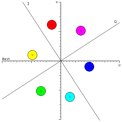
The two axes of the color chart used for Color TV are actually called U and V, and this is the origin of the term YUV encoding that you may see when choosing how to compress a picture you are saving from a paint program in JPEG format. However, for modulation purposes, two axes belonging to a somewhat rotated frame of reference, called I and Q, are used instead. However, the burst signal, which indicates the phase of the suppressed color subcarrier, is still defined as in the minus U direction. The diagram below shows the relationship between colors and the two color coordinate systems:
Of those two signals, one of them, the I signal, receives extra bandwidth, by being allowed to modulate the color subcarrier at frequencies that would take it outside the bandwidth of the TV signal if both sidebands - required to admit another independent signal in phase quadrature - were retained.
Incidentally, the color circle in the diagram above has unequal spaces for different colors in it because I used a palette I had previously created for a color triangle showing mixtures of R, G, and B on another page. A somewhat similar diagram appeared in an article about the negotiations (which ultimately failed) to establish a standard color television system for Europe, on page 106 of the issue of Electronics magazine for March 22, 1965 in the article "Colorful, faithful, easy to operate: goals for an all-European TV system" by Joseph Roizen and Richard Lipkin, which provided a comprehensive introduction to the three analog color television systems, NTSC, SECAM, and PAL.
Originally, the NTSC color system was defined in terms of three primaries which were significantly different from those now in use with color TV sets and computer monitors:
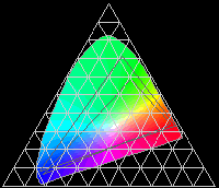
The taller dark gray outline triangle within the chart roughly indicates the older color standard, the shorter one the current one. Shortly after RCA brought out the earliest modern color TV sets in 1954, the green phosphor used was replaced by sulfide green, which had a more yellowish color, because it was easier to make shine more brightly. Some years later, phosphors using the rare-earth metals, such as Europium, were used to achieve greater brightness from the red phosphor. And the blue phosphor used was also changed to compensate for the changes in the other phosphors. Note that the smaller triangle in the diagram, showing the colors that can be reached by current display phosphors, is the area within which the colors of the diagram have a degree of accuracy.
Color television broadcasts using the CBS field-sequential system began in the United States in 1951, but the demands of the Korean War interrupted production. After it became possible to resume large-scale consumer electronics manufacturing in the U.S., the decision was made to switch to the compatible NTSC system. In late 1953, there were some NTSC broadcasts, including the first network broadcast in color of a performance of the opera Carmen on October 31, 1953, and then on January 1, 1954, the Tournament of Roses parade was broadcast in color nationwide; this was used to demonstrate color television to the public. It was not until the end of February, however, that the first NTSC color TV sets went on sale.
The Westinghouse H840CK15 was sold for $1,295 starting on February 28, 1954 in New York City. It used a unique 15" picture tube, the 15GP22, which contained both a flat shadow mask, and a flat glass plate with the phosphor dots on it, within a tube with a round front. This simplified the manufacture and design of the shadow mask.
The CT-100 from RCA was sold for $1,000 in March 1954. This 15" set also used the 15GP22. While it may not have been a problem in the normal service life of the sets, preservation of this historic television set has been complicated by a problem of air leaking into the picture tube.
RCA's next color set, introduced in November 1954, was the 21-inch 21-CT-55, which used the 21AXP22 picture tube; the picture tube was round instead of rectangular, but the phosphor dots were on the front of the tube, with that front, and the shadow mask, being spherical in shape.
The most common type of color picture tube was the shadow mask picture tube.
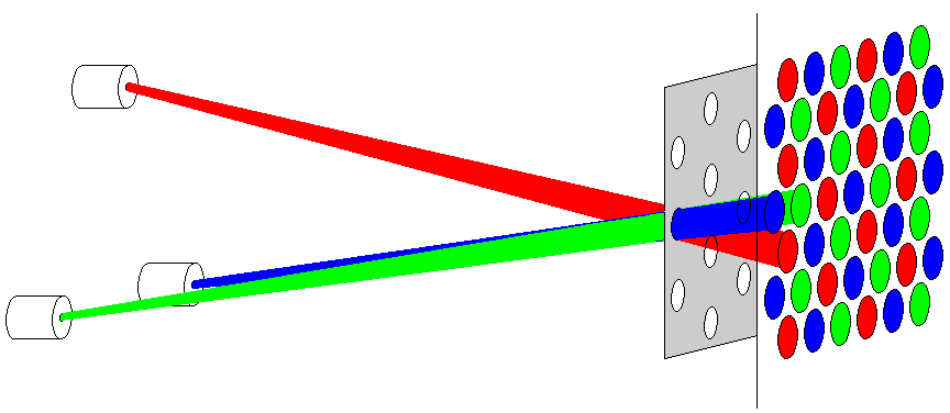
Other types of color picture tube which avoided the need for a shadow mask blocking a large proportion of the electron flux aimed at the screen were tried.
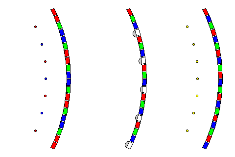
Three such attempts are illustrated above.
On the left, the principle behind the Chromatron tube is illustrated. A grid of wires behind the face of the tube is negatively charged to squeeze the beam together. If all the wires are at the same voltage, the beam is squeezed so that it hits only the green stripes. If the voltage on the wires shown in blue is slightly lower, the beam is not only squeezed, but deflected towards the blue stripes; similarly, if the voltage on the wires shown in red is lower, the beam is deflected towards the red stripes.
This design could not be made to work as well as was needed, because the wires were too close together to avoid problems - since they were at a high voltage, the voltage differences needed to deflect the beam to the blue or red stripes were too big for wires that close together.
In the centre, the principle behind the Indextron or "Apple Tube" is illustrated. A material that emits electrons when hit by an electron beam replaces every fourth stripe. In this way, circuitry in the television set is aware of the exact position of the electron beam relative to the color stripes on the face of the set, and can control the intensity of the beam based on the appropriate color component of the image.
This did not work originally because the delays in the circuits that handled the index signal were too high.
Why couldn't the index signal just have controlled the phase of an oscillator, with the output of the oscillator used to control the sequence of color signals fed to the electron beam, following the same principle that lets the color burst component of the color signal define the interpretation of the composite color signal?
In order for that to work, there would have had to have been several index stripes in an area on the left of the screen not used to display the picture, so that with each new line, the oscillator could be synchronized again. But there wasn't enough time in the horizontal blanking interval to allow the picture to be, in effect, made a little bit wider, so the color sequence had to be controlled directly by the index stripes.
On the right, the more popular and successful Trinitron picture tube by SONY is illustrated.
It uses an aperture mask of thin wires, so that little of the electron beams hitting the screen are obscured, and thus in this respect, it resembles the Chromatron tube, which was also used by Sony before it developed the Trinitron tube.
But in other respects it is very different. Instead of using only a single electron gun with a single electron beam, it uses the equivalent of three electron guns placed side by side. In the actual Trinitron tube, however, they were built into a single electron gun assembly to reduce production costs; this would also have improved alignment.
Therefore, all the wires in the aperture mask would be at the same voltage; the fact that there were three beams, all originating from a different direction, led each beam to hit the right phosphor stripe; the charge on the wires simply squeezed the beams so that they approached the screen as if they were going through a shadow mask with vertical slits, but without being blocked for most of the time.
Incidentally, while color television broadcasting began in the United States in 1954, it was not until 1966 that Canadian television stations began broadcasting in color! But this is not really as terribly late as it seems; Britain, France, and the German Federal Republic did not begin regular color TV broadcasts until the next year, 1967, and color TV was introduced in Australia in 1972, and in New Zealand in 1974. As long as television sets were made with vacuum tubes, color TV was largely a luxury for the wealthy, and not something that governments felt an urgency in facilitating. As well, the introduction of color TV in Europe was delayed by the attempt, which ended in failure, to agree on a single technical standard for color, with France sticking with SECAM while the rest of Europe chose PAL.
As well, until 1965, even NBC only presented a limited number of shows in color; it was only starting with the 1966 fall television season that all three major networks broadcast their prime time schedules in color. However, while at first only a few special presentations were in color, there were several regularly-scheduled shows in color before this: Bonanza was in color from its debut in 1959, and the Walt Disney Show was in color starting in 1961, under the new name of Walt Disney's Wonderful World of Color.
In order to retain both the advantages of the NTSC and PAL systems, I thought that it would be reasonable to use a system that might be called PAF: Phase Alternation Field. Since the relationship between phase and hue would remain constant over an entire field, the choice of an odd half-integral multiple of the horizontal scanning frequency for the color subcarrier would retain the advantage it has in the NTSC system. As phase would still reverse, even if less often, with each field instead of each line, hue would be protected against being altered by phase distortion.
The other major system considered in Europe was SECAM. This system allowed both the U and V components of the color signal to be transmitted at the full color bandwidth by transmitting only one of them with each scan line, and using a delay line to supply the other component for each given line of the picture.
To obtain the advantage of SECAM as well as that of NTSC and PAL, I proposed that instead of fixing which portion fo the color signal recieved the additional possible bandwidth, I would have it alternate between three possible directions, separated by 120 degrees in phase. But in that case, what phase angle should be the fixed point as phase is inverted with each field? Although that can be arbitrarily specified, I wanted to select a nicely symmetrical alternative. And, if the alternation takes place with each scan line, instead of each field, the fact that 1152 is a multiple of three seems to create difficulties. Note, also, that I would have had to change from the YUV or YIQ coordinate system, as my intention was to have red, green, and blue at phases spaced equally by 120 degrees, to permit one type of simple receiver.
That would require using something such as what could be called a YMN coordinate system, with equations such as these:
M  =  0.6755 R - 0.6755 G
N  = -0.390  R - 0.390  G + 0.780  B
(derived by continued fraction methods from the cosine of 30 degrees, of course) to provide the desired angular spacing. That the equation for Y would remain
Y = 0.299 R + 0.587 G + 0.114 B
would not disturb the symmetry of the equations for M and N, since even with that equation for Y, the idea is still that (0.971, 0.971, 0.971) in (R, G, B) coordinates would be a neutral white, and as confirmed by the fact that the coefficients for U and V, or for I and Q, also add to zero without first being weighted in relation to the corresponding coefficients in the equation for Y.
Given that the bandwidth of even the portion of the color signal that had more bandwidth allocated to it was significantly less than that of the black-and-white signal, however, although a compatible field-sequential set could be produced, its picture would not be sharp horizontally. But this means, of course, that all *four* major color TV systems, NTSC, PAL, SECAM, and CBS field-sequential, are drawn upon in this design. But one additional disadvantage of alternating between the directions of the three primary colors for the high-bandwidth portion of the signal is that when the direction of red is used, the conventional high-bandwidth I signal is approximated, but for both blue and green, the low-bandwidth Q signal is closer to the signal transmitted.
The fact that 1152 seems to waste bandwidth because it is greater than 1125, though, is not a problem. 1152/1125 is less than 30/24, for one thing, and, in addition, the extra 27 lines per frame can always be filled with digital information that can be used for something. Also, since there are five, rather than two, fields per frame, additional lines reserved for blanking may be required in order to provide a certain minimum number of such lines in each field.
The diagram below shows the structure of a standard North American television signal.
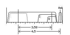
The main carrier frequency of the television signal is shown, 1.25 MHz above the start of the 6 MHz band allotted to the channel. The audio carrier is shown 4.5 MHz above that, and the color subcarrier is shown at 3.57945454545 above the video carrier.
As well, a dotted line area shows a possible unused area in the television signal; a signal in phase quadrature with the regular black-and-white television signal could be added in this area to carry additional information. When a way of adding HDTV information in a compatible manner to existing television channels was sought, it was often proposed to put digitally compressed information in this area.
While this was eventually abandoned, due to problems with the video quality of the various proposed systems offered, at the time, digital video compression technology was similar to that which is employed in the MPEG-2 standard. Today, a much greater level of compression is possible using MPEG-4, and this has led to telephone companies using the technology behind the high-speed Internet services they provide over DSL to also offer cable television over suitably conditioned telephone lines. Thus, the idea of compatible HDTV within a 6 MHz band might be worthy of being revisited given current technology.
When I was thinking in terms of my quintuple interlace color television standard, since it was all analog, I was resigned to using a band that was significantly wider than 6 MHz for a television channel. However, I had still thought there might be a way to make analog HDTV compatible with the NTSC television standard.
Let us suppose we have a bandwidth of 18 MHz. Then, let the carrier signal be 13.25 MHz from the start of the band, with a lower sideband of 13.2 MHz, and a vestigial upper sideband of 4.2 MHz.
The video signal would have the same basic characteristics as a standard NTSC video signal, with one minor change: instead of 262.5 lines per field, there would be 262.4 lines per field. Presumably, existing television receivers could cope with the extra equalization pulses required for quintuple interlace, or at least I hoped so.
The color subcarrier would retain its position in the upper sideband, and so the horizontal scanning rate would not be affected, but the vertical scanning rate would be changed from 59.94 Hz to 59.963 Hz. An HDTV color subcarrier, using the PAF (Phase Alternation Field) technique would also be somewhere in the lower sideband, perhaps about 11 MHz below the carrier. Let's take 687.5 times the horizontal scanning frequency, for a color subcarrier 10.8173077 MHz below the carrier.
Given 480 active lines in a picture for regular television, this gives 1200 active lines in an image with a 4:3 aspect ratio. But since the field rate is still (about) 60 Hz, the frame rate with quintuple interlace is only 12 Hz. What can be done?
Well, there are two places to put some additional information in the signal. The HDTV transmission might be analogue, but receivers would require a digital frame buffer of some kind.
Let us transmit a letterboxed picture with a 16:9 aspect ratio. Then, starting with a 4:3 picture with 240 active lines in each field, a letterboxed picture with a 16:9 aspect ratio would use only 180 of those active lines (thus, instead of a 1200-line picture, we are dealing with a 900-line picture), leaving 60 lines for the "black bars" at the top and bottom of the picture. Instead of having them black, they would contain picture information for 60 of the 180 lines of a second set of fields, used to increase the number of frames per second, each frame consisting of five fields, to 24 from 12. Could the other 120 lines of each of those frames fit in the other major hiding place: a signal with a 4 MHz bandwidth in phase quadrature with the video signal? So the basic structure of this video signal would look like this:

This might supply enough space for 80 lines of each of those frames, since 4 MHz is roughly a third of the 13.2 MHz bandwidth of the basic video signal. We still have 40 lines to deal with.
Since the horizontal resolution of the color signal is much less than that of the black and white signal, perhaps the vertical resolution of the color signal could also be half that of the black and white image. In that case, let the alternate frame information be black-and-white, and during the negative-image "black bars", how much information could the HDTV color subcarrier carry? For the NTSC signal, the video bandwidth was 4.2 MHz, and the color signal consisted of two signals in phase quadrature, one with a bandwidth of 1.5 MHz, and the other with a bandwidth of .5 MHz, for a total of 2 MHz, about half the black-and-white bandwith. I am envisaging that about the same relationship will apply to the HDTV color subcarrier, located about 11 MHz below the video carrier; color would be split into a component with a 1.5 MHz bandwidth, and a component with a 4.5 MHz bandwidth, for a total of 6 MHz, just under half of a 13.2 MHz black-and-white bandwidth. So that takes care of only 30 lines out of the 40 lines left over. Perhaps 8 of those lines would go to the narrowband color signal, and 22 to the wideband part. Also, note that instead of 1.5 MHz and 4.5 MHz, the diagram shows that bandwidths of 2 MHz and 6 MHz might be used in this part of the signal.
Ah, but there is a place to squeeze those last 10 lines. Remember those 80 lines transmitted in a signal in phase quadrature with the video signal? Well, in that signal, we don't have to spend any time on sync pulses and blanking and retrace, because the main video signal supplies the timing reference for everything. That lets the last 10 lines get squeezed in.
Of course, the signal-to-noise ratio will probably vary from one portion of the alternate fields to another, but you can't have everything. Upon reflection, though, there is just one little "Oopsie!" in this design. An HDTV receiver would have no trouble rejecting the 4 MHz signal in phase quadrature with the regular black-and-white TV signal; but a regular TV set, with which this design was supposed to be compatible, would not see the lower sideband of most of that signal, and therefore would have no way to disentangle most of its upper sideband from the picture.
Cutting the bandwidth of this signal in half, and moving it to yet another subcarrier, would be one possible remedy. Unfortunately, this throws off the calculations of how an alternate set of fields could just barely fit in, and so it's back to the drawing board. On the other hand, many NTSC receivers, before they invented comb filters, just turned the high-frequency portion of the black-and-white signal into mush anyways, and so perhaps this could really be termed "compatible".
As we saw in looking at how the color signal works, quadrature amplitude modulation is equivalent to a combination of amplitude modulation and frequency modulation. What was not then noted is that while amplitude modulation of a carrier by a sine wave adds signals above and below the carrier at its frequency plus and minus the frequency of the modulating sine wave, frequency modulation does the same thing, except the phase of one of the signals is reversed, and there are additional signals in the sidebands separated by multiples of the frequency of the modulating sine wave, which provide the additional noise immunity of wideband FM, making it particularly suited for quality transmission of music, as established by Edwin Armstrong. (The amplitudes of the successive signals in the sidebands are governed by Bessel functions, incidentally.) Thus, quadrature amplitude modulation is just another way of obtaining the same efficiency as provided by single-sideband transmission. This is why a receiver that doesn't see the lower sideband would see a mixture of the two signals in the sideband it does see.
But this suggests a way to solve the problem. Use quadrature amplitude modulation only in the vestigial sideband region of the original NTSC TV signal, and beyond that transmit the main signal in the upper sideband, and the applicable lines from the alternate fields in the lower sideband. But that has a difficulty as well; so far, it has been envisaged that the alternate fields would be chopped up into their component lines, and these lines stretched out to reduce bandwith, rather than using frequency division, to avoid any problems with crosstalk and changes in signal phase that would affect the image.
A cure would be to split the 90 lines to be allocated to this problematic part of the signal into three pieces. As the diagram below illustrates,

one piece would go to a signal in phase quadrature with the main video signal, but this signal would now only have a 1 MHz bandwidth, to fit entirely within the bandwidth of the original NTSC signal. What remained would be divided into two equal pieces, sent in phase quadrature around yet another subcarrier, about 3.95 MHz below the main video carrier. The same technique of isolating it from the image as used for the color signal would be applied, and so that subcarrier might lie at 3.957168 MHz below the main video carrier, or 251.5 times the horizontal frequency.
A few more details would need to be dealt with to make this actually work. The scan lines from the alternate field sequence, instead of being split up into regions each to be allocated to the different modulation methods, would be interleaved as far as possible. Since the goal is a signal with 900 active lines, derived from an NTSC signal with 480 active lines, the fact that NTSC actually has 483 active lines means that there would be room to include, with each chunk, one line containing part of a test pattern consisting of a sequence of different grey levels. This would allow circuitry to bring the components of the alternate field sequence transmitted in different ways to match one another and the primary field sequence.
Also, one of the lines in the frame could be used to supply samples of the other two subcarriers used, since the NTSC color subcarrier would have to have the back porch of the horizontal sync and blanking region to itself. The relative phase of the NTSC color subcarrier and the 4.5 MHz audio subcarrier, although it is fundamentally independent of the phase of the other subcarriers, as their frequencies are distinct, could be used to help maintain the phase of the two subcarriers between their reference signals, so much less frequent than the color burst signal, by permitting the maintenance of a high-quality time reference within the receiver. Or, a simpler solution might be to simply have the two additional burst signals immediately precede and follow the sync and blanking region, placing them on the extreme left and right edges of what would otherwise be the picture area. They could then be broadcast at different gray levels on different lines as a safeguard against phase problems as well.