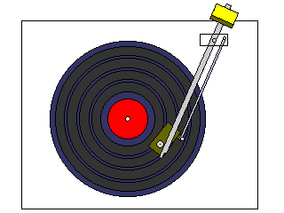
In most record players, the tonearm pivots on one point, so that the headshell, cartridge, and stylus swing out an arc over the record. But the groove on the record is oriented so that motion corresponding to sound is always precisely radial, that is, along a line going out from the center of the record.
The headshell on the end of a tonearm is at an angle with the path to the pivot of the tonearm so as to compromise between making the tonearm longer, thus reducing the angle by which the tonearm pivots to cover a distance along the record, and increasing the distance the stylus moves from the periphery of the record to the end of the grooves containing sound upon it.
There are linear-tracking turntables, some using electronic feedback, and others suspending a radially-moving tonearm on a cushion of air. Then there was the technique illustrated in the diagram below:

I trust that some of the readers of this page may actually remember the Garrard Zero 100 turntable, whose tonearm used an ingenious mechanical linkage to minimize tracking error. While the original Garrard Zero 100 turntable used traditional idler wheel drive, a later model, the Zero 100SB, which can be recognized by having a silver surround, used belt drive. One previous attempt at a tonearm that reduced tracking error through a linkage had been made over a decade previously by another British firm, Burne-Jones & Company. In that tonearm, the two rods making up the arm were obviously not parallel, converging on the headshell; in the tonearm of the Zero 100, the pivots were put on opposite sides so that instead of the arms visibly diverging as they approached the headshell, they were approximately parallel.
Older consumer turntables simply used a rubber friction wheel, which could be switched in and out as needed, to transfer motion from the motor to the turntable. This allowed changing speeds from 33 1/3 RPM to 45 RPM and perhaps even 78 6/23 RPM.
More sophisticated turntables, intended for the advanced high-fidelity enthusiast, used a rubber belt to transfer the motion of a spinning drive shaft to the turntable, providing better isolation from the vibrations of the motor, and reducing the potential for problems resulting from the idler wheel becoming flattened while the turntable sits idle. These normally would use synchronous motors.
Later, more advanced servomotors allowed the construction of direct-drive turntables, with impressive specifications in terms of the accuracy of speed and of wow and flutter. But audiophile purists were not enthusiastic about the direct-drive turntable.
In roughly the same era of the nineteen-seventies when the Garrard Zero 100 turntable was offered to the public, an interesting design attempting to combine the advantages of both approaches was made available. The Philips Direct Control turntable combined the principle of belt drive, which helps to smooth out the vibrations inherent in electrical motors, with electronic control of speed as found in direct-drive turntables. Because of the separation between the motor and the turntable provided by the belt, which was, of course, the goal of the design, the feedback loop had to be designed so that the reaction to feedback would be based on a long time-average of the feedback signal.
Even without measures such as using a linear-tracking tonearm or a design such as the Zero 100, in a conventional pivoted tonearm, while the arm may move by 20 degrees on its pivot, maximum tracking error is usually only about 2 degrees. This is because a circle centered on the tonearm pivot, with a radius somewhat larger than the distance from the pivot to the spindle, can cross the grooves of the record at an angle which is nearly a constant value, somewhere around 20 degrees. This explains the shape of a normal tonearm, with the portion containing the cartridge tilting inwards.
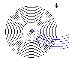
The diagram below illustrates how one can search for an optimum tonearm shape:

the black circles representing the grooves of the record, the blue arcs representing the paths of the stylus for different lengths of tonearm.
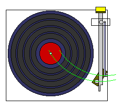
The diagram below illustrates how the Garrard Zero 100 worked.

Note that, because of where the pivots are located, the actual linkage is an irregular quadrilateral, even though the tonearm shaft and the rod accompanying it to correct the tonearm position are parallel, because of the locations of the pivots. This may not just improve the appearance of the tonearm, it may make it behave more like a conventional one as well in other respects.
The arcs show how the pivoting rod, moving around a smaller circle with a different center, will pull the headshell into a position with a smaller tilt relative to the main tonearm shaft as it moves towards the center of the record.
Since this change takes place in only one direction, although the tonearm resembles a conventional tonearm, in having a headshell tilted at a similar angle, it does differ, as the larger arc shows, by having no overhang, since the overhang of a conventional tonearm not only decreases the change of angle, relative to the grooves, over the range of the tonearm, it also causes that change to reverse direction within the record, so that the headshell can be aligned for correct tracking at two points. That minimizes tracking error for the conventional tonearm, with maximum tracking error in one direction at the beginning and end of the record, and maximum error in the other direction in the middle, but it would prevent a correction factor that continuously increases from the beginning of the record to the end from being correct.
A patent, British patent 1,342,739, was eventually received for this tonearm design in 1974, but by that time Garrard had become part of Plessey, which became the assignee of the patent. It was also patented in Canada, Germany, and Switzerland, but not the United States. In the patent, it is noted that the residual tracking error of this tonearm design is limited to an angle of 1.5 minutes.
The patent gives the four dimensions of the quadrilateral shown in the diagram; the distance from the tonearm pivot to the spindle, which matches that from the pivot to the stylus directly under the center of the main bearing, is 7.5 inches; the distance between the two pivots on the headshell is 1.5 inches, the distance along the rod controlling the angle of the headshell is 6.75 inches, and the distance between the main tonearm pivot on the plinth of the turntable to the auxilliary pivot of the control rod is 0.627 inches.
The angle between the 1.5-inch line between the two pivots on the headshell, and the direction from the tonearm pivot to the auxilliary pivot relative to the line between the tonearm pivot and the spindle are left as exercises for the reader, but they can be determined by aligning a calculation of how this arm moves with one of tracking angle errors for a conventional tonearm of 7.5 inch radius without overhang.
Recently, another pivoted tangential tonearm has become available, the Thales tonearm. It is very different in appearance from either the Burne-Jones tonearm or the Zero 100 tonearm, as it involves motion in the third dimension as well as motion parallel to the plane of the record being played.
A 1941 paper in the Journal of the Society of Motion Picture Engineers by the American engineer H. G. Baerwald worked out the conditions for optimal conventional tonearm design; one important thing to note is that it needs to be taken into account that the effects of tracking error are more serious for the inner grooves of the record, since the undulations in the groove representing the sound waves are closer together there. One approximation that can be used is to weight tracking error by the reciprocal of distance from the spindle.
An earlier paper by Erik Löfgren, cited in Baerwald's paper, proposed two alignments, the first being the same one as recommended in the paper by Baerwald which analyzed the question of tonearm design more thoroughly. Because there are additional problems with reproduction of the inner grooves of the record, in addition to the effects of tracking error being more severe there, a paper by Stephenson proposed a third arrangment more heavily favoring the inner grooves. And the turntable manufacturer Thorens has pursued an alignment standard of its own.
The Zero 100 was one form of articulated tonearm, aimed at reducing tracking error. But another class of articulated tonearm, including the Dynavector, the Vestigal, and the LOCI, was aimed at reducing the consequences of warped records through movements in the vertical direction. The last of the three is not to be confused with the first Wang Labs electronic calculator, which operated on numbers in logarithmic form.
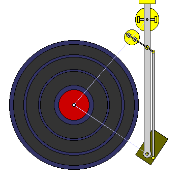
Of course, one could always take a brute-force approach to the problem to provide perfect tracking, rather than simply a much closer approximation by using a well-chosen parallelogram:

A pivoted platform, containing pullies which constrain a rod coming from the tonearm to always pass through the point corresponding to the spindle in a scaled-down analog of the turntable, would ensure that this rod follows the required tracking angle, which could then be transmitted to the headshell by a plain parallelogram.
Because the linkage between the rod and the freely-pivoted platform is not a simple pivot, but instead a constraint to linear motion over its central point, one has the same mechanical problems as are involved in building a linear tracking tonearm directly; it is very difficult to make a linkage of this sort without excessive friction. This is why mechanical linear-tracking tonearms have to rely on such expedients as air suspension to reduce friction.
Note also that instead of the rod from the tonearm resting on two pullies on a rotating platform, it might be constrained between pullies on its right and left sides, on a frame that is not only pivoted to allow it to rotate back and forth as the tonearm moves along the record, but also to allow it to tilt up and down, so that the tonearm may be lifted. Also, a cam centered on the main pivot of the tonearm could be designed so as to control the rotating platform, instead of relying on force from the rod to turn it.