
The following diagram

illustrating the instruction formats of some real computers with a 16-bit word length, shows some of the variety that is available.
The Honeywell 316 and the Hewlett-Packard 211x computers illustrate the type of simple computer which uses a bit, shown here as P, to indicate if the instruction refers to an address on the current page, or one on page zero. The I bit at the beginning of the instruction indicates indirect addressing. (This classic architecture is also exemplified by the very popular 12-bit PDP-8.) And the Honeywell 316 computer also provides for indexed addressing with one index register.
The Hewlett-Packard 2116A computer was brought out by that company shortly after Digital Equipment Corporation started the minicomputer revolution with the original PDP-8 computer in 1965, and is considered to be the first 16-bit minicomputer. Just as the PDP-8 architecture was inherited from the PDP-5, not generally considered to be a minicomputer, and which came out in 1963, the Honeywell 316 shares its architecture with earlier machines as well; the DDP-116, originally brought out by Computer Controls Corporation before its purchase by Honeywell, dates from 1964.
If one thinks of a minicomputer as something that comes, or at least can come, in a small box, like a PDP-8/S or, at most, a Hewlett-Packard 2115A or a Honeywell 316, then one could claim that the PDP-8/S, from 1966, might be the first minicomputer. The chip used internally in such HP calculators as the 9825A implemented a variation of the HP2100 instruction set, and was the world's first 16-bit microprocessor, although not made generally available.
The Raytheon 703 normally always addressed the current page the instruction was on, but it had an instruction that allowed a different page to be selected for the following memory-reference instruction.
The SDS/Xerox Sigma 2 and 3 computers, and their compatible successor the Xerox 530 either had an 8-bit unsigned displacement, or a 9-bit signed program-relative displacement. In both cases, indexing was available, controlled by the X bit, using index register 1. If the addressing was not program-relative, the S bit was used to indicate that index register 2 was used; if indirect addressing was called for by the I bit in the instruction, the value from index register 2 was added prior to indirection, and the value from index register 1 was added to the final address after indirection.
The SCC 4700 used a bit to indicate relative addressing with a signed displacement instead of a bit for current page addressing. It also had a number of two-word instructions with a full address in the second word, including optional hardware floating-point instructions.
The Varian 620 had a direct addressing mode which provided access to the first 2048 words of memory, shift instructions that shifted the accumulator an arbitrary number of places, and relative and indirect addressing, for a powerful and advanced instruction set.
The Westinghouse 2500 allocated a generous five-bit field for the opcode, and a three-bit field for the addressing mode, leaving only eight bits for the address portion of the instruction. This allowed for indirect addressing, and addresses could be absolute, relative, or indexed by one of two index registers.
The Data General NOVA computer used a very tightly packed instruction format to allow it to provide four general registers, the last two of which could serve as index registers. (In additon to 00 in the X field indicating that no indexing was taking place, the value 01 indicted program-relative addressing instead of indexed addressing. Only in the case of program-relative addressing was the displacement treated as signed.) Memory is referenced by load, store, and jump instructions; arithmetic operations are performed only between registers.
The bit marked S in the operate instruction format, if equal to 1, indicated that the result of the operation would not be loaded into the destination register, but instead would only be tested for the conditional skip condition in the instruction.
The instruction set was extended, first in the Eclipse C/350 to provide for decimal arithmetic and related operations, and then in the MV/8000 to permit 32-bit operation, by making use of the opcodes where the S bit is set, and the skip condition was either to always skip or to never skip, since then the operation performed would be irrelevant, and only one opcode in each case would need to be saved for a no-operation instruction or a skip instruction.
The Digital Equipment Corporation PDP-11 and the Texas Instruments 9900 microprocessor illustrate a more modern and symmetrical architecture. Both source and destination operands have the same form, and may either be registers or memory locations. If the operands are memory locations, the register field indicates an index register. The 9900 had sixteen general registers which were in a workspace in memory; the PDP-11 had six general registers, and could also use a stack pointer or the program counter as an index, which were denoted by placing 6 or 7 in the index register field respectively.
The addressing modes offered with the TI 9900 were:
00 Register operand
01 Register Indirect
10 Memory operand (indexed if register field not zero)
11 Register Indirect with Autoincrement
and those offered with the PDP-11 were:
000 Register operand
001 Register Indirect
010 Register Indirect with post-autoincrement
011 Indirect Register Indirect with post-autoincrement
100 Register Indirect with pre-autodecrement
101 Indirect Register Indirect with pre-autodecrement
110 Memory operand (indexed if register field not zero)
111 Indirect memory operand (indexed if register field not zero)
The Texas Instruments 980 computer, in addition to having an indirect bit, and an index bit that, as in other small computer architectures, controlled the use of one index register, had a B bit in the instruction, which determined if an address was relative to the address of the instruction in which it was found, or to the area to which the base register pointed. This was easier for compilers to handle than the type of paged addressing found on the Honeywell H-316 or the PDP-8.
The General Automation GA-16/110 and GA-16/220 were two of the earlier minicomputers from that company. General Automation was a minicomputer that was an early adopter of large-scale integration, using it to produce aggressively-priced minicomputers.
This did mean they had to use a microprogrammed design.
The 110 and 220, shown here, had both an accumulator, the A register, and eight general registers, as well as three index registers.
Basic memory reference instructions could use either a signed program-relative address or one that was a positive unsigned offset from the contents of a base register, as indicated by the P bit.
Additional instructions, which provided bits to indicate indexing, and three bits which could indicate a register operand, or further specify the opcode, had a displacement field of only five bits instead of ten bits, but the all-ones value was used to indicate a 16-bit displacement in the second word of a two-word instruction.
Register-to-register and immediate instructions were also provided.
The National Semiconductor IMP-16, which was a 16-bit computer implemented using a small bit-slice chip set before 16-bit microprocessors were available, is also shown in the diagram. In addition to four registers, it had a small internal stack.
The Wang 3300 did break memory into pages. But it had some interesting features. The page bit selected either the current page, if 1, or a fixed page, if 0, which could be either page 0 or page 1 of memory, depending on the setting of a status bit. Some instructions could have autoincrementing; for those instructions, if the A bit is set, addressing is always indirect, and so the I bit, if one, indicates the pointer is to be decremented instead of incremented.
The IBM 1130 was able to reserve seven bits in two-word instructions for functions that were only used with a limited number of instructions; the condition bits for conditional branch instructions, and the R bit used for returning from an interrupt service routine. In the single-word format, when one of the three index registers is specified, it serves as a base register in effect; when 0 is in the index field, the address field is interpreted as a displacement relative to the current location.
The instruction formats for the Control Data 1700 computer are shown in some detail here. The three bit destination register field in the register to register instructions controls three possible destination registers, so it is possible to broadcast a result to multiple registers:
001  M register
010  Q register (multiplier-quotient, or index register 1)
100  A register (accumulator)
or, if the field contains a zero, it refers to index register 2, which is the location at the high end of memory. When multiple source registers are specified, the OR of their contents is taken as the source value.
The Control Data 1700 had an interesting feature not shown in the diagram; every 16-bit word in the memory also had a program protect bit associated with it. It could have up to 32K of memory, and was intended for real-time control applications.
In the design specified by MIL-STD-1750, the two-bit base register field indicates one of general registers 12 through 15. This underscores how this design appears to have been inspired by the IBM System/360.
However, the base registers are applied only to eight-bit displacements; the address spece of this architecture, like that of many microprocessors and minicomputers, is spanned by a 16-bit address. As well, its floating-point formats are 32 and 48 bits long, making it comparable, in general capabilities, to another IBM architecture, that of the IBM 1130.
The SPIRAS-65 computer had two accumulators, A and B, and one index register X, like some other computers; but some instructions apparently used a three-bit register field to choose between not only one of those registers, but also 32-bit and 48-bit alternatives formed by concatenating those registers in the combinations AB, AX, BX, and ABX.
These different instruction formats show different ways in which small computers could cope with the fact that their word size was too small to contain both an operation code and the complete address of a location in memory. They could use various ways to make use of a shortened address to indicate a memory location, or make instructions that did not refer to memory do more of the work, or both.
While the larger computers in the Scientific Data Systems Sigma series of computers had instructions that were 32 bits long, the smaller ones had 16-bit instructions. Program-relative instructions had a 9-bit displacement field, while 8 bits were used for the displacement with other addressing modes. One opcode was instead used to indicate register to register instructions; the bit marked N usually indicated that the source operand was to be inverted before use.
The illustration above just briefly shows the main instruction formats for the computers illustrated; a later section will show, just for one very famous computer, the popular Digital Equipment Corporation PDP-8, a more complete illustration of its instruction formats.
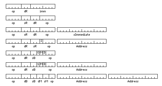
Some later minicomputers had considerably more elaborate repertoires of addressing modes, once the PDP-11 led the way. For example, here is one computer clearly named so as to endow it with a fighting spirit:
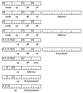
The diagram above illustrates the addressing modes of the Lockheed SUE computer. Only a subset of them is shown. Instructions can be from memory to register or register to memory. The return from interrupt instruction can use either page zero addressing or program-relative addressing, thus making a slight nod to the addressing modes of earlier minicomputers. Branches are program-relative, but there is also a jump instruction similar in format to a memory-reference instruction (but sharing its first four bits with the register-to-register instructions). Note also that there is both a long and a short format for immediate operands.
The SPC-16 from General Automation was an interesting design. Its instruction formats are shown below:

One of its most interesting features is that, like the PDP-11, it had eight registers, some of which served special purposes. Its registers were:
000 A   100 B
001 X   101 C
010 Y   110 D
011 Z   111 E
If an instruction indicated indexing, one of registers X, Y, and Z would be the index register. If base-relative addressing, which could also be considered pre-indirect indexing, was indicated, register D would supply the base address. Register E was used to save the return address of subroutines. The B and C registers could serve as extensions of register A, the accumulator, for multiplication and division.
To allow rapid handling of interrupts, the machine had a second set of registers for interrupt service routines.
One computer with a particularly complex set of instruction formats, of which the diagram below represents but a sketchy summary,
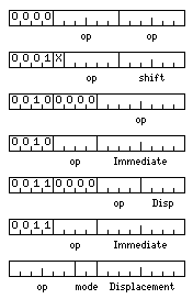
is the HP 3000 computer. The first format depicted is one in which the 16-bit word contains two 6-bit stack operations. The one with a four-bit displacement is used for input-output instructions, to indicate where a device address is on the stack.
Note that this reflects the architecture of the original HP 3000 computers; later systems in that product line used the PA-RISC architecture instead, the same one as used with the HP 9000 computers (which themselves migrated to the Itanium).
Even large computers sometimes made the effort to make instructions shorter than they would be if they included full memory addresses.
The IBM 360 computer allowed general registers 1 through 15 to be used as index registers; general register 0 could not be so used, so that zeroes in the index field of an instruction would indicate that indexing was not used. The base field acted the same way; since the contents of both registers were applied to the address in the same way, by addition, it was only a convention that one field was used to indicate the index register, and the other field the base register.
Thus, the formats of its instructions were:
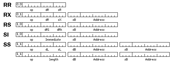
Initially, on April 7, 1964, when IBM announced System/360, they announced models 30, 40, and 50, as well as what later became models 65 and 75. Later, they introduced other models in the series. The System/360 Model 85 was notable for introducing high-speed cache memory in the form we understand it today, and it also added the ability to use two floating-point registers together for a 128-bit extended-precision quantity. Like double-precision floating-point on the 7090 and related machines, the second half of the number had an offset exponent field.
The System/360, as can be seen from the instruction formats above, was a general-register machine, with 16 registers numbered from 0 to 15. These registers could be used as accumulators, as index registers, or as base registers. Since the floating-point registers were used only as floating-point accumulators, only four of them were provided initially in the System/360 architecture. The floating-point registers were numbered 0, 2, 4, and 6. It was presumably decided to number them in this way because they were twice as long (64 bits) as the fixed-point general registers. Only much later, with Enterprise Systems Architecture/390, was a full complement of 16 floating-point registers included; for compatibility, the eight possible register pairs that can contain a 128-bit extended-precision floating-point number are (0,2), (1,3), (4,6), (5,7), (8,10), (9,11), (12,14), (13,15). It was also at this time that the ability to handle "binary floating-point", that is, floating-point numbers following the IEEE 754 standard, was added to the architecture, and the term "hexadecimal floating-point" was applied to the original floating-point format of the IBM System/360.
One low-end model, model 20, could only have a maximum memory size of 16 K bytes, and it was incompatible in that not only the optional floating-point feature was not available for it, but also 32-bit integer arithmetic, part of the standard instruction set, was omitted.
But it also had an even greater divergence from the standard 360 architecture, a modification to its method of addressing memory:
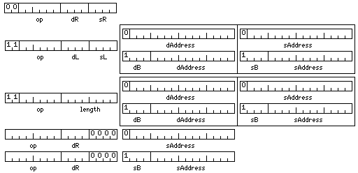
Only general registers 8 through 15 could be used as base registers. When the first bit of a 16-bit address field in an instruction was a zero, then the remaining 15 bits were used as an address, without the need to add the contents of a base register to it. Where it is shown for the memory to register instruction format, that format is simply divided into two formats, one for each case; it also applied to both address fields in the decimal and string instructions as well, and there boxes have been drawn around the address fields to show that either field could take either format. Incidentally, the Univac 9200 and 9300 also adhered to this convention.
There was actually a good reason why only general registers 8 through 15 could be used as base registers on the System/360 model 20; these general registers, 16 bits long instead of 32 bits long on this model, were the only general registers it had.
This accorded well with the regular conventions on register use on other models of System/360, where the lower-numbered general registers were used for data, and the higher-numbered ones were used as base registers or for memory pointers associated with subroutine calls.
Note that this necessitated a modification to the relocating linking loader, and to how programs would prepare object modules for input to the loader; for a normal System/360, only address constants, which were word-aligned 32-bit values, would need to be relocated, but here, when base registers were not used, the address fields in instructions would need to be relocated as well. At the least, the loader would need to make provision for 16-bit address constants.
As well, neither the System/360 Model 20 nor the Univac 9200 and 9300 computers allowed the specification of an index register in addition to a base register; instead, the field used for the index register was required to contain zeroes.
One other member of the IBM System/360 family was slightly incompatible with the standard. The System/360 Model 44 computer had a knob on the front, which could be set at 8, 10, 12, or 14. This referred to the number of hexadecimal digits in the mantissa of a double-precision floating-point number. Single-precision floating-point operations always took place on a 32-bit operand, occupying four bytes, but double-precision operations, while they could take place on 64-bit operands, occupying eight bytes, if the knob was set at 14, could also take place on 5, 6, or 7 byte-long operands for the settings of 8, 10, and 12; this allowed the highest possible floating-point speed for the precision actually required. Apparently, to maintain compatibility, regardless of the selected precision, double-precision floating-point numbers still occupied eight bytes of memory. Also, the character and decimal instructions were not available for it.
The IBM 360 architecture continues to exist to the present day, with numerous additions and extensions. This diagram shows the instruction formats that were added over the years:
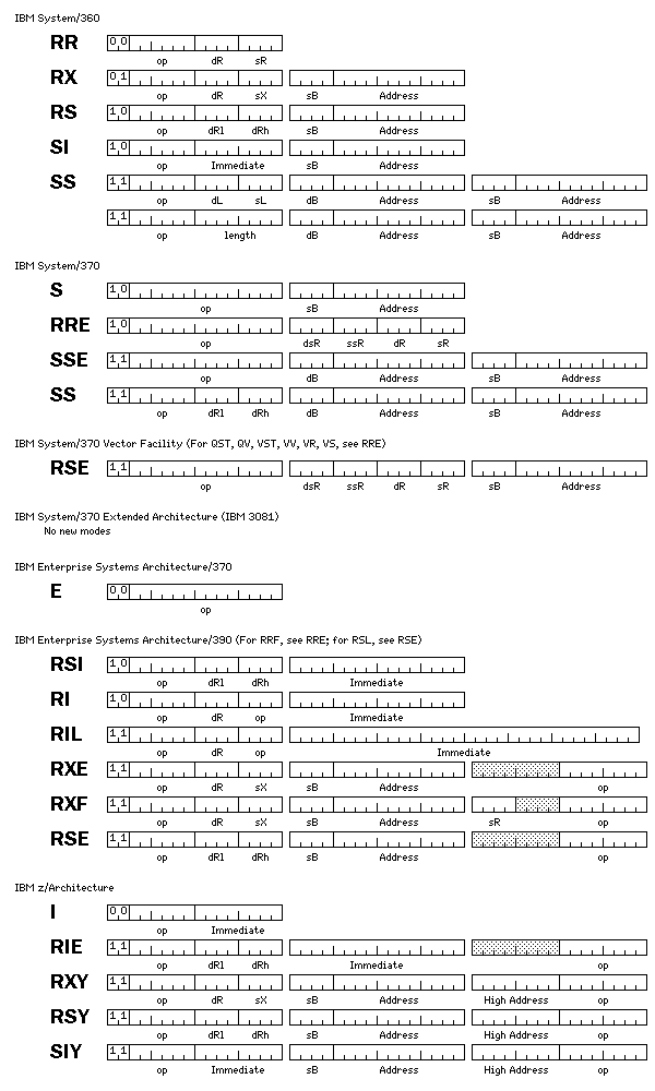
The simple rule for determining the length of an instruction from its first two bits remains in place to the z/Architecture of today. For the vector instructions, this meant that some addresses had to be loaded into registers before executing an instruction, the same expedient that the XDS Sigma computers used in order to have string instructions (since on the XDS Sigma computers, all instructions occupied exactly one 32-bit word).
The vector facility, available for the IBM 370, as well as for the IBM 370/XA, ESA/370, and ESA/390 architectures, introduced the RRE format, and used a format called RSE which was completely different from the format called RSE introduced with the ESA/390. One version of the RRE format used all four positions in the second halfword to specify registers; subsequently, only the last two were used, and instructions which used others were designated as having the RRF format.
As the IBM z/Architecture introduced 64-bit addressing, it also introduced the RXY, RSY, and SIY instruction formats, in which the displacement field is 20 bits long rather than 12 bits long. Because some of the instructions in the RXY format were previously instructions having the RXE format, and, similarly, some of the instructions in the RSY format were previously instructions having the RSE format, it was necessary for reasons of compatibility to split the address field into two parts, putting the low 12 bits of the address first, in the second halfword of the instruction, and the high 8 bits of the address in the third halfword of the instruction.
Also, several of the emulation features as provided with the IBM 370

included instructions, referred to as being of the SS format, which consisted of an instruction within an instruction, where the secondary instruction could have either RR or RX format.
The primary opcodes were:
E900  704/709/7090/7094/7094 II emulation
E901  7070/7074 emulation
E902  7080 emulation
This is the version of emulation as offered on the 370/165 and the closely related 370/168. Note that 7040 and 7044 emulation wasn't included along with emulation of other 7090-compatible machines. Interestingly enough, the method used to allocate 64-bit words in the memory of the IBM 370 to decimal addresses for 7070 and 7074 emulation involved the same principle as Chen-Ho encoding.
On the IBM 360 Model 25, 30 and 40, 1401 emulation involved additional instructions of a different sort. On the IBM Model 30 and the closely similar 25, there were a few instructions which were all in RR format for switching into emulation mode, and several other instructions in SI format for setting up the emulation or performing operations associated with the 1401. The emulation on the Model 40 relied entirely on special cases of the Diagnose instruction. While it wasn't necessary to shut down the machine to replace its microcode for emulation, the emulator only ran under DOS/360, and not OS/360, so in some installations, where the machine was normally used with OS/360, a restart would have been required to switch over to emulation.
RCA, in 1966, announced the Spectra/70 series of computers, made from monolithic integrated circuits, which had the same user mode (but not privileged mode) instructions as the System/360. This line of computers was taken over by Univac in September, 1971. Before this happened, Univac first made the 9200 and 9300 computers, which were IBM compatible and which, having a line printer built in, or being built into a line printer, were smaller-scale systems, but then introduced, in 1968, the 9400, which was more clearly a large mainframe. Planned later models in that series were modified to integrate them with Series 90, which is what the Spectra 70 computers became when offered by Univac.
The two lower-end members of the Spectra/70 family, the 70/15 and 70/25, were also not fully compatible with System/360. Unlike the System/360 model 20, or the Univac 9200 and 9300, they did not change the form of addresses.
However, while they still had general registers used as base and index registers, these were accessed only with the load multiple and store multiple instructions. In addition to the instructions for packed decimal arithmetic, these machines had a set of instructions with a similar format for binary arithmetic, with a four-bit length field for each operand. The System/360 architecture already included instructions for AND, OR, and XOR that had the format of the MVC instruction with a single 8-bit length, and these Spectra/70 models made use of them as well.
Interdata constructed minicomputers which were originally a compatible subset of the IBM 360, but when they came out with successor systems with expanded capabilities, they extended them in a different manner:
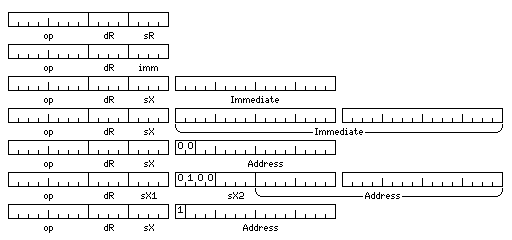
They added a short form instruction with a four-bit immediate operand, as well as instructions with immediate operands that could be either 16 or 32 bits long, and which could have the contents of an index register added to them (as would be the case in a load effective address instruction). Normal memory-reference instructions could either have a plain 14-bit address, for compatibility with earlier Interdata machines, a 24-bit address which could be indexed by two index registers at once if desired, or a 15-bit program-relative address.
Another series of computers inspired by the IBM System/360, this time one which directly competed against some of the lower-end IBM mainframes, was made by Memorex:
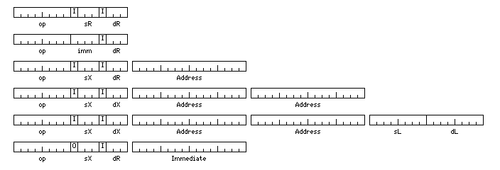
In this architecture, only eight general registers were used, but a fourth bit was used with each field specifying a register to indicate indirect addressing. Thus, register indirect addressing was included in the architecture. As well, there were two forms of immediate addressing, one with a four-bit value in the first 16 bits of the instruction, and one where indexing could be specified to cause contents of a general register other than register 0 to be added to the immediate operand before use. This was termed direct addressing, thus the add instruction of that form was termed ADDD, Add Direct, instead of, say, Add Effective Address.
Another architecture that was even more similar to the System/360 was the Wang VS line of computers. Its instruction formats were as follows:
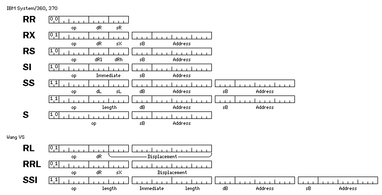
The RL and RRL format instructions were branch instructions which included a 20-bit or 16-bit program-relative displacement instead of using base-displacement addressing.
The SSI format instructions were string instructions that provided for a single-byte immediate value, and lengths that could be independently specified for the source and destination instructions, at the cost of adding instructions 64 bits in length to the architecture.
The Wang VS had other interesting differences from the System/360 and 370.
Floating-point instructions for single- and double- precision numbers had the same 8-bit opcodes; the first bit of the destination register field was used to indicate which form of the instruction was used.
Also, a decimal floating-point type was provided, the format of which was almost identical to that of double-precision floating-point, except that the mantissa was composed of BCD decimal digits instead of hexadecimal ones.
Another computer inspired by the System/360, but with very different instruction formats nevertheless, is the Sigma; this computer had a 32-bit instruction word, and will be discussed below along with other computers with that type of instruction. Not only its data formats, but the number of registers, the amount of addressable memory, and the instruction repertoire were chosen to make a machine equal in power to the System/360, but, due to a more traditional design, less expensive to produce, despite being made from discrete transistors.
Numerous machines were made that had the same instruction set as the System/360. IBM itself used a different designation, 4 Pi, for computers sold to the military that had the 360 instruction set.
The Union of Soviet Socialist Republics redirected its computer efforts to the Unified System of computers. Such machines as the Ryad EC-1040 were compatible with the System/360, and were believed to have been partially designed through information obtained by espionage activities.
The People's Republic of China produced the series 200 computers which were compatible with each other, the DJS-210 having a 16-bit word, and the DJS-220 and DJS-230 having a 32-bit word. Some sources note that having a compatible series was inspired by the IBM System/360, while others claim these machines were imitations of the 360 with the ability to run the same software.
Information about the early computers of the People's Republic of China, however, seems to be scarce, and thus it is hard to definitely determine which version of this is correct. Also, the DJS-130 is said to either resemble, or be a clone of, the Data General Nova (but which?), and the relationship of the DJS-180 to the PDP-11 is similarly unclear.
Later, a plug-compatible computer industry arose in the United States, leading to such computers as the Amdahl 470/V6, the Itel AS/5, and the Magnuson M80.
Gene Amdahl was, of course, the designer of the IBM 360 architecture; he left IBM out of frustration with the company not pursuing an opportunity to make larger systems in that line. Itel was a company that purchased 360 mainframes and then leased them to others which then went on to include memory made for it by National Semiconductor for them. Fujitsu was a partner of Amdahl, and continues to make plug-compatible machines; first National Semiconductor, and then Hitachi, which had been the actual maker of the CPUs, acquired Itel's plug-compatible business.
Also, there was the Two-Pi computer, a computer made with bit-slice technology that was an attempt to offer mainframe power in the size of a minicomputer.
Incidentally, Magnuson Computers was founded by Carl Amdahl, the son of Gene Amdahl, and his partner in Trilogy Computers. As I recall, this was all amicable; Amdahl computers made the larger computers, and Magnuson the smaller ones.
A while back, I had heard of a company called Standard Computer, that made perhaps the only IBM 7090 clone ever attempted. I had not known of their IC 9000 computer, a microprogrammable computer clearly designed to facilitate imitation of the IBM 360 instruction set; there is a preliminary manual for it on Al Kossow's site, and I have heard the claim that this computer was actually constructed and sold. It may have been sold to OEMs that later resold it as their own plug-compatible machine rather than directly to end-users, which would explain why I hadn't heard of it before.
A circle spans either 360 degrees or 2*pi radians, but a sphere comprises 4*pi steradians; IBM's military version of the 360 was largely used in avionics, the air being a realm of freedom of three-dimensional movement (thus, it was not that IBM could not count that it used the name 4 Pi and left the 2 Pi trademark lying around), and one of the later versions of it, the System/4Pi model A-101S, serves still on the Space Shuttle.
However, while all the original models of the System/4 Pi computer resembled the IBM System/360 in the sense of using two's complement arithmetic and being oriented around the 8-bit byte and power-of-two multiples of it, of those three models, the models TC, CP, and EP, only the model EP was actually compatible with the 360. Thus, for example, in the model TC, instructions were 8, 16, or 24 bits in length; 16 bit instructions began with a 1, and the others began with a 0. The model CP had an instruction format strongly resembling that of the IBM 1130 computer, and may have been compatible with it.
IBM's later System/3 computer had a very simple and regular instruction format, which it shared with the System/32:
![]()
The mode bits had the following values:
00 16-bit absolute address
01 8-bit base-relative address, base register 1
10 8-bit base-relative address, base register 2
11 no operand
Although the opcode field was only four bits long, the machine could have up to 64 instructions, since whether an instruction had two operands, no operands, or only a source operand, or only a destination operand, also determined what instruction it was.
The byte shown as the length field was actually called the Q byte, and was used for various purposes in different instructions, but a length field was one of its most common uses.
The IBM Series/1 computer, on the other hand, had a more complicated and thus more compact and flexible set of instruction formats, some of which are shown in the diagram below:
The diagram below

attempts to illustrate the native instruction formats of the Digital Equipment Corporation's famous VAX computers, which also, at least in their early models, included PDP-11 emulation. An instruction consists of an opcode, which may be one or two bytes long, followed by as many operands as needed. The diagram shows the two opcode formats, followed by the operand formats. One possible value for the bits indicating the operand mode instead indicates a prefix byte for the operand which indicates an index register.
This diagram shows the instruction formats for the justly famed Cray-1 computer:
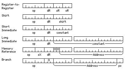
Addresses point to 64-bit words, and thus two additional packet select bits are required in branch instructions, where a unit of 16 bits is referred to as a packet.
Memory-reference instructions have only a four-bit opcode field because only loads and stores are done on main memory, following the same practice as with RISC computers.
And now, here are seven computers with 32-bit instructions, and four others with 30-bit instructions:
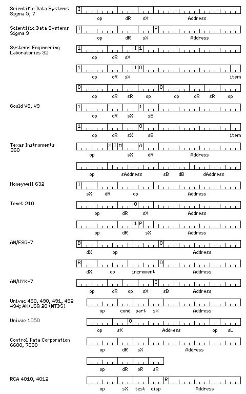
The first instruction format shown is the instruction format for the SDS Sigma series of computers, for which all instructions were 32 bits long.
This computer was an attempt to design a computer that might be arguably just as good as a System/360, only simpler in design, and therefore cheaper to make. It used EBCDIC internally for characters, and it used the same floating-point format as the System/360 for positive numbers, but negative numbers were indicated by two's complementing the corresponding positive number instead of by merely setting the sign bit.
It had sixteen general registers, each 32 bits in length. Only registers 1 through 7 could be used as index registers, allowing a three-bit index field in instructions.
The address space covered 524,288 bytes; thus, instructions contained a 17-bit word address, and did not require a base register. If an instruction was indexed, the index was taken to be in terms of the operand length, thus allowing the use of bytes and halfwords in positions other than the leftmost part of a word through indexing.
Registers 12 through 15 were a packed decimal accumulator, so in decimal instructions, the destination register field instead served as a length field.
Character string instructions omitted the index field, and lengthened the address field by three bits to allow a byte address. The destination register field (usually) indicated a pair of registers, containing the other information needed to specify the instruction.
Register-to-register instructions were simply memory-reference instructions referring to the first 16 words of memory; but the registers were kept in fast semiconductor memory instead of core. The machine also had memory mapping and protection; the memory was divided into 256 equal parts of 2,048 bytes, and each one had an associated two-bit storage key.
The general registers were also used as the floating-point registers.
The Sigma 9 computer allowed the use of a 22-bit physical address by using a page select register; the first bit of the address field of the instruction could be used to choose between page zero of memory, if it was zero, and the 65,536-word page of memory indicated by the six bits of the page select register if it was one. This was used in Real Extended Addressing, so that programs could use the entire memory of the computer, and is somewhat reminiscent of the addressing methods used with such computers as the PDP-8 or the Honeywell 316.
The Sigma 7 computer introduced memory mapping to the Sigma line; the first eight bits of the 17-bit address field within the instruction were translated to indicate the address of the page actually used. This feature, also present on the Sigma 9, was how user programs accessed memory above the first 131,072 words; they did not use the first bit of the address field to access a larger quantity of virtual memory.
For compatibility with Sigma 7 operating systems in installations with 131,072 words or less of memory, it was also possible to have a memory mapping mode where the entries in the memory map were shorter, remaining within the 131,072-word memory capacity of the Sigma 7 instead of the 4,194,304-word memory capacity of the Sigma 9. (Note that since there are four bytes in a word, while virtual addresses are shorter on the Sigma, physical memory addressing embraces 16 megabytes, thus matching that of the IBM System/360.)
Later, Xerox made the Xerox 550 and Xerox 560 computers which were compatible successors of this series; there was also a computer called the Xerox 530, but this was a computer with a 16-bit word and a 48-bit floating-point type, and so it was not compatible.
The second instruction format shown in this illustration is that of the SEL 32 computer from Systems Engineering Laboratories. A 32-bit word could contain either one 32-bit instruction or two 16-bit instructions, but a 32-bit instruction had to be aligned on a 32-bit boundary, which is similar to how instructions in 48-bit or 60-bit words were handled on many Control Data computers.
This computer is particularly interesting for how it avoided wasting space in the addresses of aligned operands. The first of the two instruction formats shown is that for byte operands, which have a byte address. In the second format, a word address is given, and so the last two bits are used to indicate whether the operand is a 32-bit word, the left or right 16-bit halfword of the target word, or a 64-bit doubleword. Before that, an extended addressing mode was available that allowed addresses to be extended by one bit, from 19 bits to 20 bits, by allowing values in the index register to have a larger range. As well, memory mapping was included in the SEL 32/70, which allowed a 24-bit physical address.
A later version of the computer made after SEL was acquired by Gould had an alternate base register mode, which allowed 24-bit virtual addresses.
The Texas Instruments 960 computer, in its single-address instruction format, included a bit, shown here labelled by the letter M, to indicate an immediate operand, and an A bit to indicate the instruction would use, of two banks of registers included in the architecture to provide for fast context switching, the one opposite to that currently in use, in addition to bits for indirection and indexing. The index register was indicated by a three-bit field in the instruction.
The fourth instruction format shown is that of the Honeywell 632 computer. This computer was a minicomputer with a 32-bit word, unlike the Sigma computers, which were mainframes with a 32-bit word, but the basic memory reference instruction format for this computer included the same fields, with the same lengths, but in a different order, as that of the Sigma.
The fifth set of instruction formats shown are the memory-reference instruction formats of the TENET 210 computer. This computer had the interesting feature that if the indirect bit of the instruction was set, only registers 1, 2, and 3 instead of registers 1 through 7 could be used as index registers, so that a bit was available to distinguish between pre-indexing and post-indexing.
The sixth set of instruction formats shown are those of the legendary AN/FSQ-7 computer, made for IBM for the SAGE (Semi-Automatic Ground Environment) defense project. This is the computer whose front panel, with a record number of blinking lights, was prominently featured on the television show The Time Tunnel, as well as appearing in many other movies and television shows. This computer had the unusual characteristic that its arithmetic instructions dealt with vectors of two 16-bit numbers.
The seventh instruction form is that of the AN/UYK-7.
The eighth instruction format shown is that of the Univac 460, 490, 491, 492, and 494 computers, as well as the NTDS (Navy Tactical Data System) computer, also by Univac, which was essentially identical to the Univac 460. This architecture also served as the basis for the AN/UYK-7 computer (which, however, had its word size expanded to 32 bits).
One interesting feature of this architecture is that most instructions contained a three-bit field indicating when the next instruction should be skipped. This field was also used in a conditional branch instruction, however, so it would seem it was primarily useful in actually allowing single instructions performing a calculation to be skipped, instead of facilitating conditional branches.
The ninth instruction format is that of the Univac 1050. It competed against the IBM 1401. However, this computer did not have a field bit in the six-bit characters it stored; instead, there was a length field in the instruction, as later used on the IBM System/360. All instructions were 30 bits in length; the machine's internal registers, stored in low memory, were called tetrads, and were 24 bits in length. Also unlike the 1401, but like the 360, it performed binary arithmetic as well as decimal arithmetic. Interestingly enough, when Univac replaced this computer with a newer one aimed at the same markets and applications, often used as an auxilliary computer to larger systems, it replaced it with the 9200 and 9300 computers, based on the IBM System/360 Model 20, described above.
The tenth set of instruction formats shown is that of the Control Data 6600 computer and its successors. This computer had a 60-bit word; 15-bit and 30-bit instructions could have any positions within the word, but a 30-bit instruction could not cross a word boundary; this restriction simplified the circuitry for instruction fetch and decoding, thus speeding the computer.
The eleventh instruction format is that of the RCA 4100 series of computers. In addition to a six bit opcode, a three-bit index field, and a 14-bit address displacement, a three bit field indicated the condition to be tested after the instruction, with another three bit field indicating how many words to skip if the condition was met. And one bit was used to indicate returning from an interrupt, and apparently also for cooperative multitasking.
And here are the formats of the 64-bit instructions of the Model 757 vector computer from the People's Republic of China:

The two formats are those of arithmetic and jump instructions respectively.
In the arithmetic instructions, the bit marked S indicates the instruction is a scalar instruction instead of a vector one; the bit marked L indicates a load from memory is involved instead of a store to memory; the bit marked R reverses the sense of the bits contained in the control register.
There are three operands, so arithmetic operations are performed by calculating (source) op (operand) and storing it in (destination). The second operand of the operation is always in a register, while the source and destination may be in memory.
The I bit controls a form of incrementing not precisely specified in my source.
In the jump instructions, the D and L bits are named as the dispatch and locator flags respectively. That the field marked disp is used for jumps of up to 64 instruction lengths backwards (indicated by the locator flag) is speculation on my part.