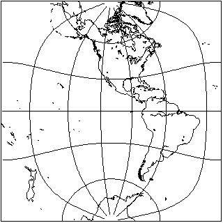
Let us first start the story of this projection by looking at how a hemisphere can be projected with the techniques used on the previous page:

This is half of a map of the world shown on that page which presented the world as two hemispheres in that form.
Of course, maps can be presented from different viewpoints, and on that page a map was also shown where the poles were in the centers of the hemispheres. If one took the middle part of that map, one could also have a map of a hemisphere with the poles at the top and bottom, but it would still look very different:
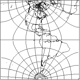
Although both maps are ways of conformally mapping a hemisphere to a square, they are still mapping the hemisphere to two different shapes, because in the case of the second projection, the perimeter of the map corresponds to part of the Equator as well as the meridians that bound the hemisphere.
For a map of a hemisphere, of course, the second alternative is not a particularly appealing map. But this kind of projection, modified to show the whole world instead of a hemisphere, happens to be very useful as an intermediate step in drawing a conformal projection of the world on an ellipse.
The contour plot of the arcsine function on the complex plane looks like this:

This time, rather than setting up my map drawing program to draw this, I took an image from a mathematics textbook from 1898. The lines are drawn on the graph to points corresponding to the complex sine of zeta plus i times eta.
As the diagram illustrates, the lines corresponding to a constant complex part of the argument of the function, and its additive inverse, join to form ellipses with the points -1 and +1 as their foci; the lines corresponding to a constant real part are hyperbolae with the same foci, which intersect the ellipses at right angles.
So, if one were to fit the whole world on the second map of the hemisphere in a square shown above, giving the square a width of pi, and centering it about the origin, then the sine function would nicely fold over to touch the areas where the equator is split, and the boundary of the ellipse would correspond, as expected, to the bounding meridian which is assigned to the top and bottom of the square. And to map the world, rather than a hemisphere, to the ellipse, of course the same trick as used for the Lagrange projection would be applied.
This would also apply to rectangles of other shapes drawn along the same lines with a different modulus for the elliptic function, allowing the eccentricity of the ellipse to be varied.
A conformal projection of the world on an ellipse on these lines was first described by Oscar Sherman Adams in 1925, but the formula he gave for calculating it was slightly in error, leading to the Equator not quite reaching the two sides of the bounding ellipse, so that there were two tiny cuts on the edge of the map that were too small to notice. This could have been the result of uncritically taking a formula for conformally mapping a circle to an ellipse that was given by H. A. Schwartz in an 1869 paper, Conforme Abbildung der Oberfläche eines Tetraeders auf dei Oberfläche einer Kugel, volume 70, pages 121-136. The reference given by Adams gave the page number incorrectly as 151.
For an ellipse twice as wide as it is high, the consequence of using the wrong rectangular projection is subtle and hard to see; for an ellipse with a 3:2 aspect ratio, on the other hand, it is a severe error which would have been spotted immediately.
The error was corrected by André Gougenheim in 1950; I believe that the paper first containing the corrected projection was Sur une Nouvelle Famille de Planisphères Conformes, Annales Hydrographiques, series 4, volume 1, pages 169-186.
Subsequently, in 1965, Laurence P. Lee independently made the same correction in his paper Some Conformal Projections Based on Elliptic Functions, Geographical Review, volume 55, number 4, pages 563-580.
The error had been noted, but assumed to be an inevitable consequence of a conformal projection to the ellipse, in the 1944 book World Maps and Globes by O. M. Miller and I. Fisher.
Here is an example of this projection, in the corrected form:
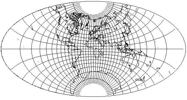
This one was drawn with 0.997 as the parameter for the elliptic integral; that meant the intermediate rectangle had an aspect ratio of 2.73117, while the resulting ellipse has an aspect ratio of 1.92633. Such a large aspect ratio for the intermediate rectangle meant that if the ordinary rectangle had been used, the resulting imperfection would have been hard to notice.
Another example,
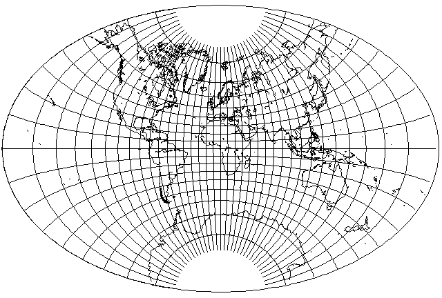
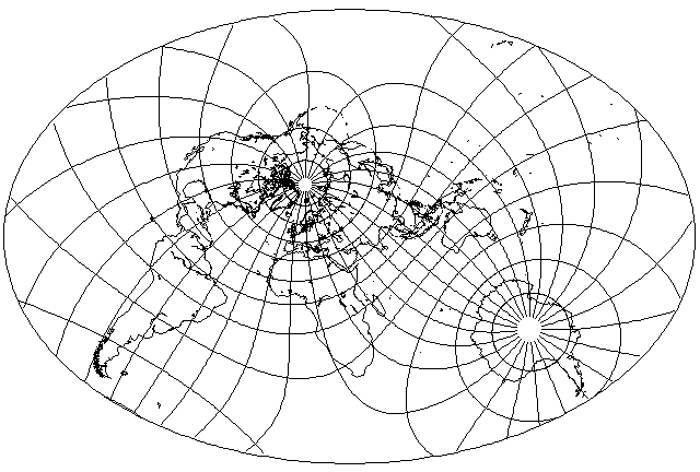
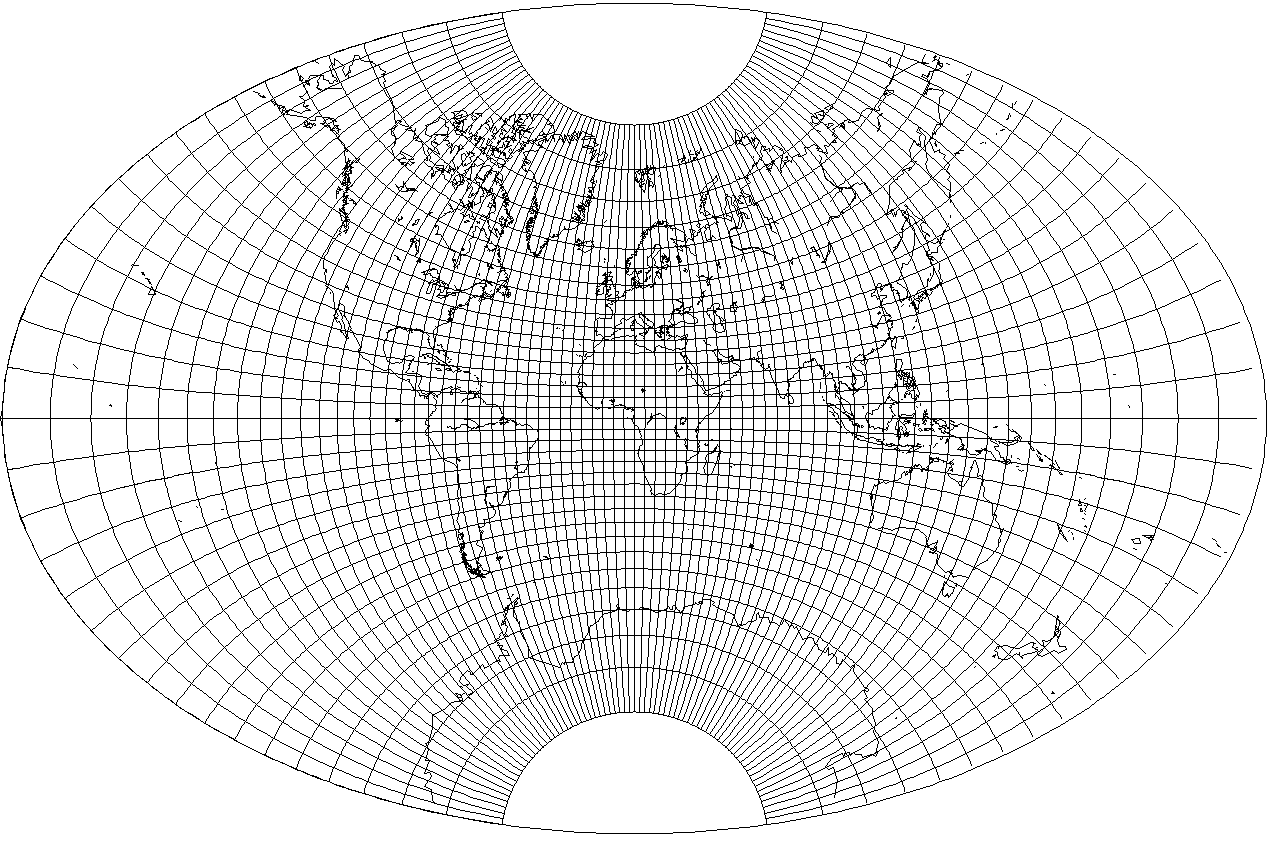
uses a parameter of 0.97, so the aspect ratio of the rectangle is 1.993881, and that of the ellipse is 1.52166.
And here is the projection with the same parameter value, but in the oblique aspect used in illustrating several other projections on these pages:
In fact, I felt this projection looked so nice that I did it again in the conventional aspect, but in a larger size:
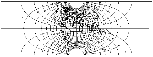
When the ellipse has a 2:1 aspect ratio, the error is a subtle one, but when the aspect ratio is 3:2, it is unmistakable. Here is an example where a projection with and without the ratio are compared, where the parameter is 0.9975, so the aspect ratio of the world in a rectangle is 2.789287 and the aspect ratio of the ellipse is 1.95958.
Here is the normal conformal projection of the world on a rectangle, the precursor to the incorrect version:
And here is the incorrect version of the world in an ellipse produced from it:

Then this is the modified conformal projection of the world on a rectangle, the precursor to the correct version:

And here is the correct version of the world in an ellipse produced from it:
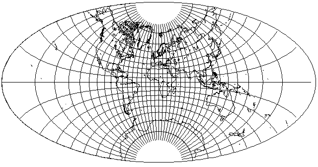
As can be seen, the difference between the correct and incorrect versions is a subtle one at this aspect ratio; the outer meridians are just a bit flatter than one would expect.
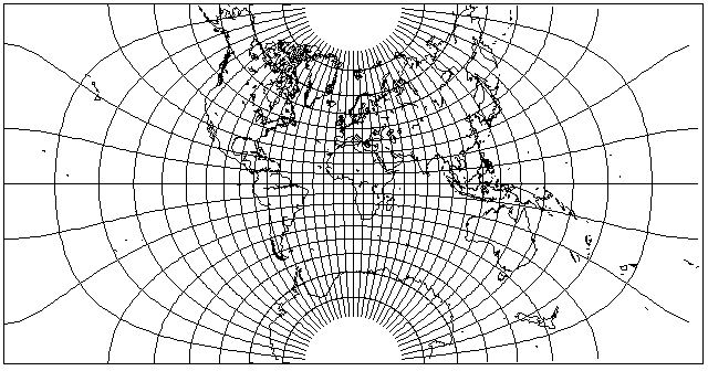
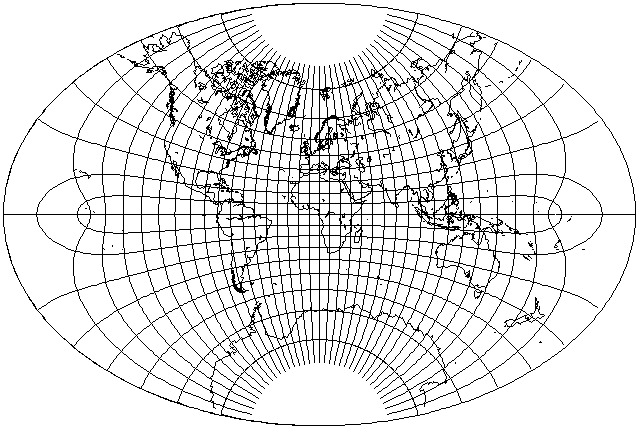
And then here is the same sequence, where the parameter is 0.965, so the aspect ratio of the world in a rectangle is 1.943995 and the aspect ratio of the ellipse is 1.495888.
Here is the normal conformal projection of the world on a rectangle, the precursor to the incorrect version:
And here is the incorrect version of the world in an ellipse produced from it:
Here is the modified conformal projection of the world on a rectangle, the precursor to the correct version:

And here is the correct version of the world in an ellipse produced from it:
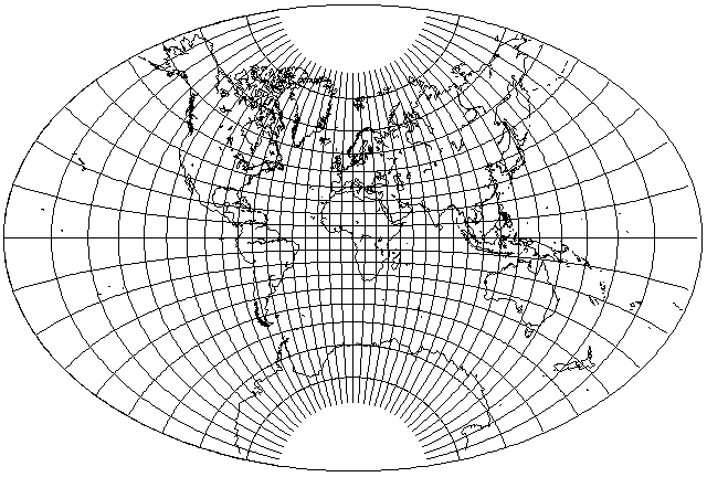
At this aspect ratio, the difference is obvious, because the sine function is now stitching together parallels that are actually drawn on the map in the incorrect version - and meridians actually drawn on the map in the correct version.
If we magnify the incorrect version of the conformal projection of the world on an ellipse at the higher aspect ratio, from what we saw:

to this detailed image of a portion of the projection, with lines of latitude and longitude drawn at one-degree intervals,
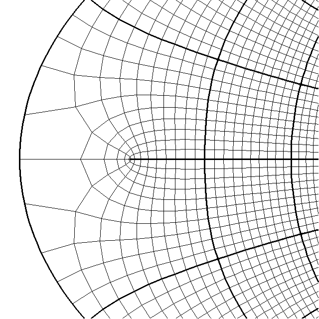
we can see that it has the same type of error as the projection with the less elongated aspect ratio, just smaller in size.
If one did not insist, however, on conformally mapping the sphere to a mathematically perfect ellipse, one could have avoided all this trouble, as well as the need for the use of elliptic integrals, simply by making use of the symmetrical ovals that closely resemble ellipses which are the parallels of latitude on the Transverse Mercator.
Thus, take the Lagrange Conformal Projection of the world on a circle; map it back to the globe by inverting the Stereographic with an extent of 75° matching the border of the Lagrange Conformal Projection, and then the Mercator yields:
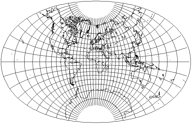
One can widen the oval a little, by increasing the extent to 80°, and still get a result that looks like an ellipse:
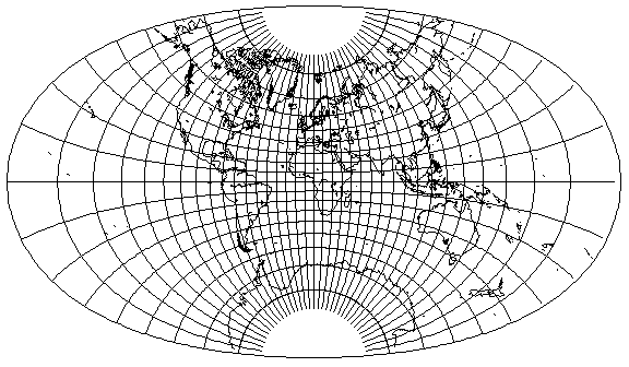
But when it is widened further, however, by increasing the extent to 85°, then the oval is noticeably flattened at the top and bottom,

which means that if one wants a 2:1 ellipse to match the Mollweide and the Aitoff-Hammer, one will likely have to resort to elliptic integrals.
This diagram shows how
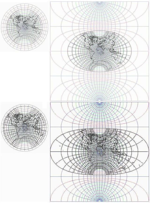
mapping the Lagrange conformal projection on a circle to a different portion of the hemisphere leads to it becoming mapped to a region on the Transverse Mercator with a different shape.