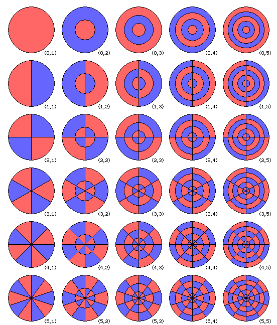
Many physics textbooks include a diagram such as the following:

This illustrates the vibrational modes of a circular membrane clamped all over its perimiter.
The differential equation governing the motion of such a membrane has solutions which involve a radial part and a circumferential part; the circumferential part is a trigonometric function, and the radial part is a Bessel function.
I will not touch, here, on the mathematics involved beyond what was noted above. Instead, the illustration above, of a relatively simple vibrating system, is here to introduce the idea that more complex systems can be treated in a similar fashion.
For each mode, the black lines are the "nodal lines", where the vibrating system would not move if it were vibrating in that mode alone, and the red and blue areas show where the vibration would be opposite in phase. Of course, the extent of the motion is greater in the middle of each region, and least at the edges as the nodal lines are approached, but I simply drew a simple diagram with a solid color for each area.
One early view of the first six modes of the violin back plate (the f-holes making the front plate more complicated) is as shown in the diagram below:

Here, the outer border of the plate is not to be considered a nodal line, as these are modes of a free plate, not one clamped at the edges.
The above is based on computer plots in the pioneering 1987 work of George Knott, using the NASTRAN finite-element software package on a Cray X-MP computer.
Carleen Hutchins' October 1981 Scientific American article included a photograph of an actual violin back plate, showing its first six modes by means of hologram interferometry; the modes displayed looked similar, with only the sixth one being somewhat different:

In this diagram, the modes are numbered, as these numbers are used to refer to them.
If the plates of a violin are more complicated than a simple clamped circular membrane, still more so is the body of the violin as a whole.
Also, different designations for the violin modes are used by different authors. Fortunately, keys to the nomenclature are available:
| Hutchins | Rossing | Jansson |
| A0 | A0 | A0 |
| A1 | A1 | A1 |
| B-1 | B1 | C1 |
| B0 | B2 | N |
| cbr | C1 | C2 |
| B1- | C2 | T1 |
| B1+ | C3 | C3 |
The notation in the first column, due to Carleen Hutchins, is most commonly found, particularly in works for the use of violin makers, but it is also used in scientific papers on violin acoustics.
But scientific papers on violin acoustics may also use one of the other two sets of designations for the modes as well, the one due to Thomas D. Rossing, or the one due to Erik V. Jansson, both of whom have written a number of very important papers on the subject.