Welcome to the home page of the Concertina II computer architecture.
The original Concertina computer architecture was originally intended as a simple example of a conventional old-style CISC architecture, to help explain how computers work. It was expanded over time to include many features from a wide selection of historical computer architectures, to explain those as well.
Concertina II was intended as an ISA that could conceivably be of practical use in an actual implementation. However, I cannot make ambitious claims for it, as my experience in this area is quite limited. This architecture went through quite a number of drafts before I felt that I had struck an acceptable balance between the various factors that had to be compromised to provide the architecture with the capabilities I sought.
However, I believe that the current version of the ISA is a sound basis on which to proceed, and I only expect to be changing it with minor tweaks as I continue to flesh out the architecture and describe its features.
Once I have it completed, it may serve as an alternative to RISC-V, even though the designer of that architecture is far more knowledgeable and experienced than I am. This is because I feel it may at least suit some people's tastes more than RISC-V does.
What is the Concertina II ISA, and what choices were made in its design?
The Concertina II design is still unfinished; many parts of it are yet to be described, and, although I do not intend to tear it up and start afresh, as I no longer feel I will be able to do better, it is still subject to minor tweaks.
It will be freely available to all to implement without restrictions once completed, subject to export controls on computer technology.
The basic Concertina II instruction set is largely patterned after today's most popular type of ISA (instruction set architecture) design, RISC (reduced instruction set computing), but it does not qualify as a genuine RISC design by any reasonable contemporary definition of RISC, even the least puristic.
The basic instruction set consists of 32-bit instructions, but also adds the ability to use a pair of 16-bit instructions at any point in the sequence of instructions in place of a 32-bit instruction.
This allows increasing code density by using smaller instructions for many operations, without losing the simplicity of fetching and decoding instructions gained by having all instructions of the same length.
As in many RISC designs, there are two main register files, one for integer values (with registers that are 64 bits wide) and one for floating-point values (with registers that are 128 bits wide), each of which contains 32 registers.
Also, the memory-reference instructions are of the load-store variety, following standard RISC practice.
The following extensions to the RISC model are included in the most basic portion of the instruction set:
It is precisely because base-index addressing is provided by restricting potential index registers to registers 1-7, and potential base registers to groups of 7 (which group depends on the displacement length) that this design does not qualify as RISC, and instead could be called CISC in RISC clothing.
Typically, RISC architectures normally only allow two registers to be indicated in a memory-reference instruction. One is the destination register of the instruction, and the other one is the one the contents of which are added to the displacement to form the effective address, Since a base register is needed for any memory access when the displacement is not large enough to indicate any location in the available memory, this means that the advantage of having an index register isn't available, and array access require additional explicit arithmetic instructions to compute addresses.
Thus, since the use of arrays is a very common operation, full base-index addressing was considered a very important feature to add.
In order to make it possible to provide this feature, the integer registers were split up into groups of eight so that the index register and base register fields could be only three bits long instead of five bits long, thus allowing both to fit in an instruction.
Normally, if one allocates a block of memory containing 65,536 bytes, using a base register to point to that block, it is not useful to have addressing modes that can only access the first 4,096 bytes of that block. Therefore, separate groups of registers are used as the possible base registers for different sizes of displacement values.
Only one register serves as the implicit base register for 15-bit displacements; this is done to allow one larger block of memory to be used in conjunction with those accessed with 12-bit displacements. This permits more compact memory-reference instructions, and is inspired by the System/360 Model 20 computer.
The above summarizes how the basic instruction set of this computer was designed to take the basic RISC design, and offer important extensions to it, while still having instructions that fit in 32 bits.
But a number of other extensions are also offered. These require going beyond the somewhat RISC-like model of the basic instruction set, and instead recognizing that this architecture also has VLIW (Very Long Instruction Word) characteristics.
Instructions are grouped in blocks of 256 bits, each of which contains eight 32-bit instruction slots. If feasible, an implementation aiming for maximum performance should have at least a 256-bit data bus to main memory, permitting a block of instructions to be fetched at once.
A small portion of the opcode space for instructions is dedicated to codes which represent headers instead of instructions.
Headers, if any, are processed before the instructions in a block are decoded.
After the headers are processed, or after it is determined that the block does not begin with a header, the computer has the information required to decode all the instructions in the block in parallel.
One of the most important features that having headers provides, which is still considered part of the basic instruction set of the Concertina II architecture, is pseudo-immediate values.
Some register-to-register instructions may have a source register specification replaced by a five-bit byte pointer to an address within the current instruction block, which points to an operand for that instruction.
This capability is supported by headers which contain a three bit decode field, which indicates that some of the eight 32-bit instruction slots in the current block are to be ignored during instruction decoding, and skipped over in execution, so that pseudo-immediate values can be placed in them.
What are pseudo-immediate values, and why are they included in this ISA? Essentially, they are inspired by the Heads and Tails design of Heidi Pan. As Mitch Alsup has reminded us all in the design of his "My 66000" ISA, immediate mode instructions have the advantage that a constant value can be used in a calculation without requiring an additional fetch of data, with all the delays and overhead of memory accesses in modern architectures, where DRAM is slow compared to processor logic.
This is because the immediate value is part of the instruction itself, and thus has already been fetched as part of the instruction stream.
But since data items come in several widths, comprehensive support of immediate values means that instructions must come in many different lengths, and I felt this would complicate their decoding to an unacceptable extent.
With pseudo-immediate values, the length of the instruction doesn't have to be changed. A pointer to the value only takes up the same space as a register specification.
But if the value is fetched from a location indicated by a pointer, it isn't an immediate value any more. Hence the term "pseudo-immediate" - given that instructions are fetched from memory in 256-bit blocks, and the data to which the pointer refers is within the same block as the instruction itself, even though the values are not actually immediate values, they still offer the same basic advantage as immediate values. (To some extent, of course, this depends on how the implementation handles the instruction stream. Specifically, to gain the full advantages of this, the entire block needs to be buffered within the processor during instruction decoding.)
In addition to pseudo-immediate values, headers allow two basic sets of features to be added to the ISA that go beyond the RISC model.
Thus, while the architecture initially has the appearance of a conventional RISC architecture, it is intended to combine the basic features and advantages of RISC, CISC, and VLIW architectures.
Note, however, that by VLIW, I mean modern VLIW architectures, such as the Itanium or, even more particularly, the Texas Instruments TMS320C6000 chip, and not the type of classic VLIW architecture the term was originally concieved of as referring to, such as that of the Control Data Cyber 200 computer.
Given that both the Itanium and the i860 were failures in the marketplace, despite being backed by the might of Intel, it is understandable that some might doubt my sanity in proposing a VLIW design in this day and age.
However, instead of including a break bit in every instruction, the break bits are in an optional header at the beginning of a 256-bit block of instructions. Implementations don't need to be designed around VLIW operation, but they can be, if they are aimed at a niche where a VLIW design is appropriate.
There are 32 integer general registers and 32 floating-point registers, and those instructions that perform arithmetic or logical operations include a bit for enabling changes to the condition codes as a result of those instructions. These are characteristics found in RISC architectures.
Having register banks of 32 registers allows different calculations to be intertwined in the code, and being able to control if instructions affect the condition codes allows more intervening instructions between an instruction that sets the condition codes and a branch instruction that makes use of those results. Both of these things allowed code to be designed to offer some of the same benefits as are obtained from out-of-order execution, without the hardware overhead. However, at the microprocessor clock rates in use today, these measures normally are not enough to be effective: however, if code written this way is combined with simultaneous multi-threading (SMT), then there is still the potential for competing with out-of-order execution.
Also, the architecture provides extended register banks of 128 integer registers, 64 bits in width, and 128 floating-point registers, 128 bits in width, which will also promote efficient VLIW operation.
Instructions are organized into 256-bit blocks which contain eight 32-bit instruction slots.
These blocks are always aligned on the boundaries of aligned 32-byte areas in memory, so an instruction slot that may contain the initial header of a block must have an address the last five bits of which are zero.
When a block header makes provision for instructions longer than 32 bits, it is possible that these instructions may cross block boundaries, depending on the rules applicable to the particular block header format in use. Specifically: the Type I block header does allow instructions to cross block boundaries; as these block headers support related instruction sets, it is also possible for instructions to cross from a block beginning with one of these three types of header into an instruction block beginning with this kind of header. In this case, the instruction set available is determined by the nature of the block in which the instruction begins; that it may continue into a block in which an instruction of its type cannot be indicated is not to interfere with its successful execution in a conformant implementation.
The instruction set is organized so that the computer is able to fetch a 256-bit block of instructions, and, after processing any block header within the block, to determine what, if any, special processing is required, immediately begin decoding each 32-bit instruction slot independently of the others in the block.
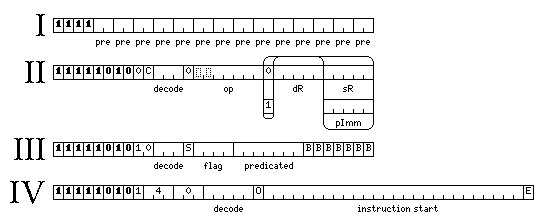
There are four different types of block header, which are shown in the diagram below.
Four types of header are illustrated in this diagram. The first three of them are required to provide the functionality that will be described here. The fourth one, although described here, is not a part of the architecture as currently defined; it may be added in future to permit an expansion of the instruction set.
The first type of header allows for instructions of different lengths to be freely mixed. This is achieved by having fourteen two-bit prefix fields in the header, each of which corresponds, in order, to the remaining 16-bit halves of the seven remaining instruction slots in the current instruction block.
These fields each indicate what is contained in the corresponding 16-bit area of the instruction block, and are interpreted as follows:
00 A 17-bit instruction starting with 0
01 A 17-bit instruction starting with 1
10 The start of an instruction 32 bits in length or longer
11 Not the start of an instruction
Note that the prefix value of 10 must always be followed by the prefix value of 11. An invalid combination where this is not the case is used to distinguish the remaining types of header, so as to avoid the need for additional opcode space for those headers.
Also note that the prefix code 01 may also indicate the start of an additional instruction longer than 32 bits which is located within some opcode space not used by the 17-bit short instructions.
The second type of header also functions as a two-operand register-to-register operate instruction, as well as a header which, with its decode field, specifies the number of 32-bit instruction slots at the end of the block which are not decoded as instructions, but are instead reserved for other purposes, such as the data values for pseudo-immediates.
The decode field is used to indicate the number of 32-bit instruction
slots that are reserved for data other than instructions, such as pseudo-immediate values,
for which no attempt is to be made to decode them as instructions. A value of 000
in the decode field indicates that all the remaining instruction slots are
to be decoded as instructions; a value of 001 indicates the last instruction
slot is to be reserved, and not decoded, and so on.
An immediate value in an instruction allows it to perform an arithmetic operation involving a constant without having to perform a fetch of data from memory in addition to the fetching from memory already performed as part of reading in the instruction stream.
An important design goal of the Concertina II architecture has been to drastically simplify the decoding of instructions; once a 256-bit instruction block has been checked for a header, and that header, if present, has been processed, all the instructions in the block can be decoded in parallel independently. The varying lengths of different data types mean that including a wide selection of instructions with immediate values would conflict with this.
A pseudo-immediate is addressed by a pointer in the instruction, which seems to be the same thing as a memory-to-register instruction making use of a constant value stored somewhere else. However, the pointer is a short-range one, which only points to a location within the same 256-bit instruction block as the current instruction is contained in.
Therefore, although it involdes a pointer reference, and thus is not "really" an immediate, hence the name "pseudo-immediate", it provides the same advantage of the constant argument having been fetched as part of the instruction stream!
This second type of header reserves space for these constants which therefore won't be decoded erroneously as instructions, and because the header is also an instruction, it lets these three bits of information be provided without the overhead of using a full 32-bit instruction slot for a header and nothing else.
The third type of header provides supplementary information which allows the computer to provide VLIW functionality.
The primary feature of this type of header is to provide for VLIW features which can be used to accelerate the speed of instruction execution, particularly on lightweight implementations of the architecture which lack out-of-order execution.
There are seven bits marked B, for break; they correspond to the seven remaining 32-bit instruction slots in the block, and if a bit marked B is set, this indicates that the instruction in its corresponding instruction slot may not be executed in parallel with the instructions that precede it.
|
Important note: it is intended that this ISA may be implemented in a number of ways. Specifically, in relation to the VLIW feature of the break bit, these three classes of implementations are possible:
In consequence, any programs which would produce a different result on the first two types of implementation listed above are to be considered to be invalid programs which have been written incorrectly. Thus, the architecture specification requires implementations to execute code which does not contain any explicit indications of parallel execution with sequential consistency. When code does contain such indications, implementations may follow those indications, or they may execute the code sequentially, even if different results are produced in the two cases; it is the programmer's responsibility, if consistent model-independent execution of programs is desired, only to indicate parallelism where it does not lead to results different from those of completely sequential code. |
In this header format, there is also a four-bit flag field. This indicates which of the sixteen flag bits may be used for predicating instructions in this block. A seven-bit predicated field indicates which instruction slots contain an instruction the execution of which is conditional, based on that flag bit. There is also a bit marked S, for sense; if that bit is zero, a predicated instruction will execute if and only if the selected flag bit is set (equal to 1); if it is one, the predicated instruction will instead execute if and only if the selected flag bit is cleared (equal to 0).
The decode field has its usual meaning in this header.
There is a provision for allowing the execution of instructions longer than 32 bits in blocks with this type of header; it is not particularly efficient, but it avoids the complexity of defining an additional header type. Since the extended register banks of 128 registers are particularly useful in code designed to be efficiently pipelined without the use of advanced out-of-order execution techniques, and many of the instructions designed to make full use of those registers are 48 bits long, it appeared that this feature was useful to provide.
To execute an instruction that is 48 bits or longer within a block with a Type II or Type III header, the following is required:
The executable 32-bit instruction slot corresponding to the place in the instruction stream where this long instruction is to be executed shall contain:
This technique is possible since instructions 48 bits in length or more are distinguished from regular 32-bit instructions by their first few bits within blocks with a Type I header, where they normally occur.
The five bit pointer is in units of bytes, thus 0 refers to the start of the current 256-bit instruction block, 1 to the next 8 bits, up to 31 for the last 8 bits in the instruction block. The first few possible values, of course, would never be used; 0, 1, 2 and 3 are within the header, and 4, 5, 6, and 7 are within the first possible executable instruction, so they can never be valid.
The three zero bits can be replaced by 001, 01x, or 1xx to
permit the specification of additional long instructions, or (which takes priority) the five-bit
pointer can be replaced by 00xxx to allow the specification of additional instructions
which remain entirely within the 32-bit instruction slot.
Such additional instructions, if defined, will serve specialized purposes such as privileged operations.
The fourth type of header, should it come to be used, will function as follows:
The decode field may contain a number from 0 to 24, indicating the number of bytes reserved at the end of the current 256-bit instruction block for pseudo-immediates or other supplementary data.
The instruction start field contains one bit corresponding to each remaining
byte in the current instruction block after the header. Normally, if a bit in this field is a
1, it means that byte begins an instruction. However, there is an important exception
to that rule. Remember that short instructions in this architecture are 17 bits long, rather than
16 bits long. Since there are no 8-bit instructions, a 17-bit instruction can be unambiguously
indicated by immediately following the 1 which indicates the start of the instruction
by another 1.
This same technique is applicable to other lengths of instructions. So this type of header increases the opcode space available for instructions in several ways:
The bit marked E is a 1 if the block is followed by either
1, or
The purpose of this bit is to permit the immediate decoding and execution of the last instruction in the block if it is complete within the block, but no subsequent instruction starts within the block to unambiguously indicate that it is complete.
The bit marked O is 1 only if the block is preceded by a
block with a header of Type IV, and the portion of the instruction start
field in that block not excluded by that block's decode field from those
which correspond to bytes containing instructions ends in an odd number of ones.
The purpose of this bit is to simplify the use of the instruction start
field in the current block for instruction decoding by preventing apparent ambiguities at
the beginning because of it not being possible to easily distinguish, when there are several
17-bit instructions starting with 1 in a row, whether it is the 1
bits in even or odd positions which start new instructions.
The basic complement of registers included with this architecture is as follows:
There are 32 integer registers, each of which is 64 bits in length, numbered from 0 to 31.
Registers 1 through 7 may be used as index registers.
Register 8 serves as a pointer to a table of pseudo-operations, if this feature is used.
Registers 9 through 15 may be used as base registers, each of which points to an area of 1,048,576 bytes in length. This addressing format is used for 48-bit extended memory-reference instructions.
At least part of the area of 3,072 bytes in length pointed to by register 16 will normally be used to contain up to 384 pointers, each 64 bits in length, for use in either Array Mode addressing or Address Table addressing.
Registers 17 through 23 may be used as base registers, each of which points to an area of 4,096 bytes in length.
Register 24 serves as a base register which points to an area 32,768 bytes in length.
Registers 25 through 31 may be used as base registers, each of which points to an area of 65,536 bytes in length.
There are 32 floating-point registers, each of which is 128 bits in length, numbered from 0 to 31.
Floating point numbers in IEEE 754 format have exponent fields of different length, depending on the size of the number. For faster computation, floating-point numbers are stored in floating-point registers in an internal form which corresponds to the format in which extended precision floating-point numbers are stored in memory: with a 15-bit exponent field, and without a hidden first bit in the significand.
As 128-bit extended floating-point numbers are already in this format in memory, all floating-point numbers will fit in a 128-bit register, although shorter floating-point numbers are expanded.
However, the 32 floating-point registers may also be used for Decimal Floating-Point (DFP) numbers. These numbers will also be expanded into an internal form for faster computation, but that internal form may take more than 128 bits.
This is dealt with as follows: Only 24 DFP numbers that are 128 bits in length may be stored in the 32 floating-point registers. When such a DFP number is stored in an even-numbered register, it is stored in that register, and the first 32 bits of the following register. When it is stored in a register the number of which is of the form 4n + 1 for integer n, the first 84 bits of the internal form of that number are stored in the last 84 bits of that register, and the remainder of the internal form of that number is stored in the last 84 bits of the second register after that register.
In this way, the same principle that storing double-length numbers in two adjacent registers is respected: numbers too long to be stored in a given register are stored in that register, and in another register of the same register file that is nearby. But the method is extended to allow more efficient use of the available space.
This technique is also required for handling the new 128-bit floating-point type included in the latest IEEE 754 standard; this type is similar to the 32-bit and 64-bit types in having a hidden first bit, and is not the same as this architecture's usual 128-bit floating-point type. And a similar technique will also be required for handling the new 256-bit floating-point type also in the latest IEEE 754 standard.
There are 16 short vector registers, each of which is 256 bits in length.
Each of these registers may contain:
As well, they may contain sixteen 16-bit short floating-point numbers in one of two formats.
These numbers all remain in these registers in the same format as that in which they appear in memory.
The entire set of 16 short vector registers can contain a table of bits used for bit-matrix-multiply operations on 64 bit binary words. As well, the short vector registers may also be used as four string registers, each 128 bytes in length.
This is done, rather than using them as two string registers, each containing 256 bytes, because four registers are the minimum number of registers required for the general register style of operations, at least as claimed in advertising literature for the Data General Nova. Having these strings only half the maximum length of those available to memory-to-memory string operations is presumed to be accessible, since strings "really" only have to be at least 80 characters long, as everyone knows.
In addition to the basic set of registers, two other larger sets of registers are also included in the architecture:
A set of 128 64-bit integer registers, and a set of 128 128-bit floating point registers.
A set of 8 vector registers, each of which contains 64 storage locations for floating-point numbers, each one 80 bits wide. This allows the computer to process vectors of 72-bit floating-point numbers in addition to vectors of 64-bit floating-point numbers, if the optional variable memory width feature is included.
As for how data values are stored in memory:
Signed integer values are stored in binary two's complement format.
Floating-point numbers are stored in IEEE 754 format, but in addition there are instructions for processing data in the format originally used by IBM's System/360 computers, including the Extended Precision format introduced on the Model 85.
The architecture is big-endian: the most significant bits of a value are stored in the byte at the lowest numbered address.
As well, there are 16 flag bits which are used for instruction predication, and of course there is a 64-bit program counter. The program status quadword includes eight alternate sets of condition codes in addition to the normal set of condition codes, and the program counter and flag bits are also part of the program status quadword.
In general, as with most other computer architectures, instructions are provided to jump to a specified location in memory to continue execution.
In this architecture, instructions are considered to fall on 16-bit boundaries.
The normal rule for branch instructions is that their targets must be executable instructions. There are exceptions to that principle, as well as another special consideration, which apply to this architecture, however.
Athough these points might seem obvious, it should also be obvious that it is advisable to state them explicitly to avoid the possibility of confusion.