This teletypewriter enciphering machine was bulky and expensive and complicated. Swedish cryptanalysts under Arne Beurling cracked the cipher of the simplest variant of this machine, the T-52a and T-52b.
The British never achieved a regular penetration of T-52 messages. It had appeared that, at least during the war, that the only T-52 messages they deciphered were messages that belonged to pairs sent with the same key, but they were able to determine how the T-52 worked from those messages.
One part of the reason for this is that many messages encrypted by the T-52 were sent over land lines, which the Swedes, but not the British, had the opportunity to intercept. But another reason was that the T-52 was used to encrypt high-level strategic traffic for the Luftwaffe, which also sent similar messages using Enigmas. Thus, attacking the T-52 was lower in priority than attacking the Lorenz Schlusselzusatz, which was used to encrypt high-level strategic traffic for the German Army, or Heer, which, although it did use Enigmas for tactical messages, did not generally use them for messages with information of strategic importance.
I have recently seen, on the Web, the information that, in 1984, the British Government finally revealed that, indeed, Sturgeon had been cracked during the war, so the issue of a lack of intercepts must have been somehow overcome. In addition, it was noted that the XOR matrix between the pinwheels and the paper tape in the T52c was, in fact, a complication whose contribution to security was illusory - there was also a note that, after the war, it was discovered that Siemens added this to the design on its own, and failed to heed the advice of Germany's military cryptanalysts, who had seen this and who had better modifications to suggest.
It may also be noted that the final version of the machine, the T-52e, which included two improvements which previously appeared separately in the T-52c and T-52d, seems to be a very secure design, although the use of cams instead of resettable pinwheels was a serious flaw.
Ten wheels, in this machine cams whose pattern of 0 and 1 positions could not be modified, of sizes 73, 71, 69, 67, 65, 64, 61, 59, 53, and 47, which were called A, B, C, D, E, F, G, H, and K respectively, provided the raw material for this machine's cipher.
In additon to having their states sensed at the primary tap point, producing the output that was XORed with the plaintext characters or controlled their shuffling, they were also sensed at a point 25, 24, 23, 23, 22, 22, 20, 20, 18, and 16 positions earlier, respectively.
This additional position controlled the movement of the wheels, so that they stepped in an irregular fashion.
The way in which the wheels stepped can best be explained by an oversimplified form of that motion. Each wheel moved unless both of two possible conditions was met, in which case it was prevented from moving: In the simplified model:
These wheels remain still:
  A   B   C   D   E   F   G   H   J   K
if
 ~C   C  ~E   E   G  ~G   J  ~J   A  ~A
and
 ~B  ~D   D   F  ~F  ~H   H   K  ~K   B
Note that the twenty conditions involved both the extra tap on each wheel and its inverse, and no wheel controlled itself. Since every wheel had to be either 1 or 0, and the condition was OR for movement, at least five of the ten wheels had to move with this arrangement, so although the wheels controlled each other, they could not get stuck in a state where they never stepped.
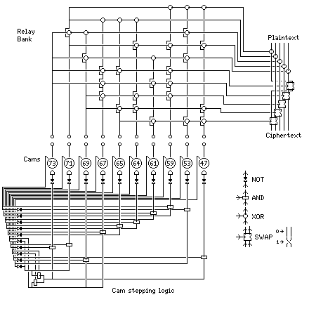
Mechanically, this worked as follows: both the plus and minus connections to an electromagnet were controlled by relays, so the electromagnet was energized only if the relays at both ends allowed current to flow. The magnets were interposer magnets: if active, they prevented the cam they controlled from moving.
From the main sensing position on the cams A through K, ten signals were derived, labelled 1, 3, 5, 7, 9, and I, II, III, IV, and V, that performed the actual operation of modifying the plaintext to produce the ciphertext.
I through V were XORed with bits 1 through 5 of the plaintext character. Then bits in the character were swapped: 1 caused (if its value was 1 instead of 0) bits 1 and 5 to be swapped; signals 3, 5, 7, and 9 swapped bits 4 and 5, 3 and 4, 2 and 3, and finally 1 and 2.
First, bits A through K were exchanged, by a simple plugboard on the T52a, T52b, and T52d, and by a set of switches that performed the same function as a plugboard on the T52e, and by an elaborate set of five switches with eight positions on the T52c. Then, in the T52c and the T52e, the ten signals went into a bank of relays, so that each of the signals, 1 through 9 and I through V, that performed the actual encipherment was the XOR of several cam outputs.
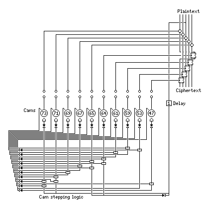
The following is a diagram of the T52e:

Circles, except when they are sockets or plugs for a plugboard, are XOR gates. The rectangles are AND gates. The black and white hourglasses are inverters. The wide white hourglasses swap the two inputs from the top to form the two outputs at the bottom depending on the input from the side. The logic being relay logic, wired-OR is present.
The T52e, shown here, included all the features that this telecipher acquired over its development. The extra features, over and above a simple set of ten cams controlling XORs and swaps of plaintext bits, are divided into two groups; one group was also present only on the T52c, and the other group was also present only on the T52d.
The relay bank was also present in the T52c, but it was wired differently. The T52c also had a means of altering the order in which cam outputs went to the relay bank, but instead of a plugboard, it was a set of five eight-position switches, each one controlling three swaps of the cam signals.
The T52d did not have those features, but it did have cam stepping logic; again, that logic was somewhat different from that of the T52e.
Here is a diagram of the T52c:
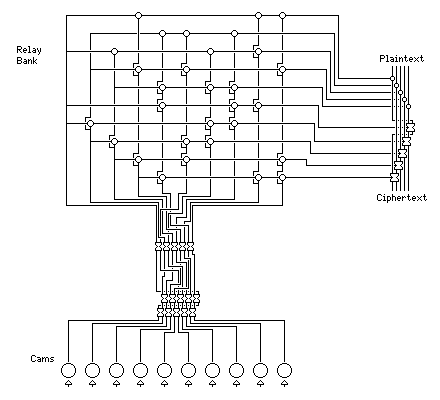
In this diagram, the switch-controlled swaps should be considered to be positioned as follows:
  3  6  9 12 15

   2  5  8 11 14
  1  4  7 10 13
and the five switches control the fifteen swaps as follows:
    1  2  3    4  5  6    7  8  9   10 11 12   13 14 15
   -----------------------------------------------------
 P  0  0  0    0  1  0    0  0  1    1  0  1    1  1  1
 S  0  1  0    1  0  0    0  1  1    1  1  0    0  0  0
 T  1  0  0    0  0  1    1  0  1    1  1  1    0  1  0
 U  0  0  1    0  1  1    1  1  0    0  0  0    1  0  0
 W  0  1  1    1  0  1    1  1  1    0  1  0    0  0  1
 X  1  0  1    1  1  0    0  0  0    1  0  0    0  1  1
 Y  1  1  0    1  1  1    0  1  0    0  0  1    1  0  1
 Z  1  1  1    0  0  0    1  0  0    0  1  1    1  1  0
And here is one of the T52d:
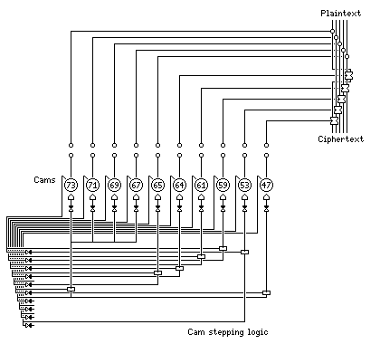
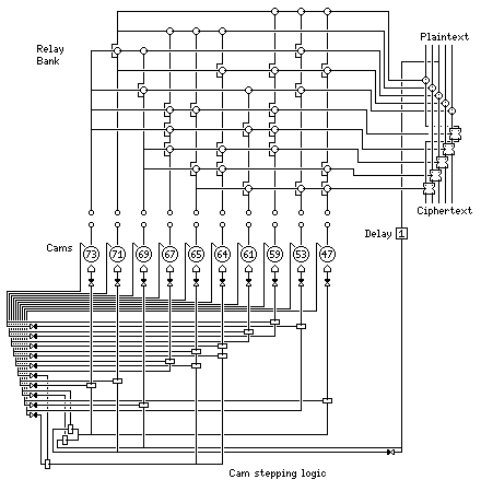
The T52d and T52e are shown here in the "ohne Klartextfunktion" mode. They also had a feature where the third bit of a plaintext character, after a delay, was introduced into the cam stepping logic, which was also changed in that mode. This limited autokey, or "clear text function", caused serious problems of garbling in practice, and was therefore little used.
However, that does not prevent me from including diagrams of the T52d and T52e in this mode, particularly as the stepping logic is somewhat more symmetrical in this mode in both cases.
First, the T52e "mit Klartextfunktion":
then, the T52d "mit Klartextfunktion".
Next
Chapter Start
Skip to Next Section
Table of Contents
Main Page