Quadibloc 24 is a cipher with a 128-bit block size partially based on a division of the block into three areas of 40 bits in length and one area 8 bits in length. A division such as that was originally envisaged as the basis for the block cipher that became Quadibloc II, but with the 8-bit area performing a nonlinearity control function. Instead, in this design, the 8-bit area is altered by the round, and nonlinearity control, corresponding to the expansion permutation in DES, is achieved when the 80-bit input to the f-function is split into a 16-bit nonlinearity control part and 64 bits to be the conventional input to an f-function with a 64-bit output.
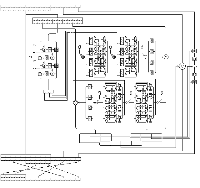
The Quadibloc 24 round is shown below:

Quadibloc 24 is envisaged as having at least 16 rounds, although of course 32 rounds would be preferable.
The design is oriented around two sources of strength.
One byte of the block is altered by three bytes of the f-function output. Thus, it becomes difficult to work backwards from that byte to discover what three bytes were used to modify it, and the relationship between inputs and outputs for that byte is very flexible. Of course, modifying one byte three times in one round, or modifying it once in two other rounds in a more conventional structure might seem equivalent, and five bytes of the f-function output do not receive similar protection.
The sixteen bits of the block that are used for nonlinearity control go through four Feistel rounds involving a key-dependent S-box before its bits are used to select one of two S-boxes for stages in the two standard Quadibloc f-functions. This encipherment, therefore, is deeply embedded in the round, making it difficult for the cryptanalyst to attempt to reconstruct S-box S9. With only two possibilities, however, it might be thought that correlation attacks are possible; however, given that there are two stages, considering only the effects of the nonlinearity control bits, five of these bits control each byte of the output from the f-function.
Both of these intended sources of strength in the cipher come from the fact that ten bytes of input to the f-function are reduced first to eight bytes of output from the f-function and then to six bytes of the block that are modified by the round. The first reduction involves a hidden encryption of two bytes before it is used to select S-boxes, and the second reduction involves enciphering one byte by three bytes of f-function output.
Also, because of the way in which the eight byte f-function output is applied to the last six bytes of the block, and because the contents of S9 would not be symmetrical, despite the fact that each layer of the Quadibloc f-functions in the cipher uses only one S-box four times, the cipher is not vulnerable to an attack based on rotational symmetry.
Quadibloc 24 uses the following S-boxes:
Each round of Quadibloc 24 acts on a block of 128 bits, which will be considered as being composed of 16 bytes, numbered from 1 to 16 from left to right.
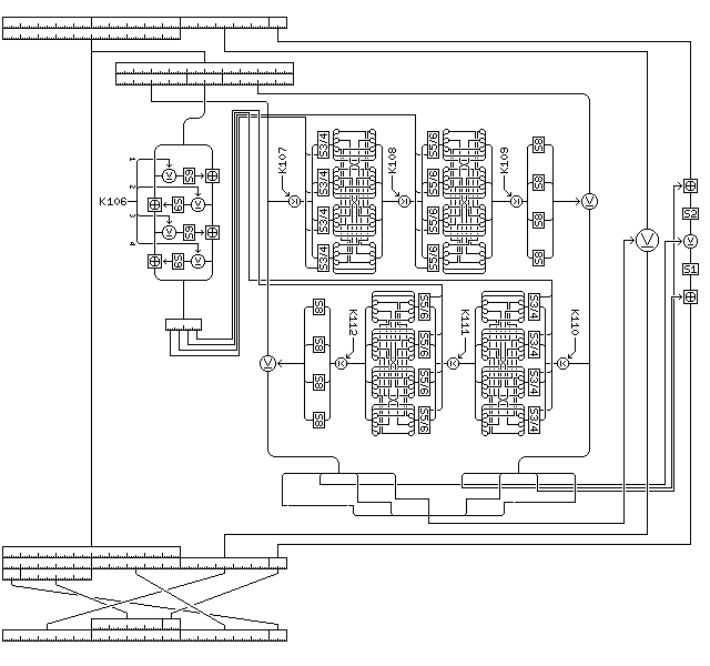
Each round uses seven 32-bit subkeys, which are K1 through K7 in the first round, K8 through K14 in the second round, and so on until the sixteenth and last round which uses K106 through K112.
In each round, a copy of the first ten bytes of the block, bytes 1 to 10, is made and is used as the input to an f-function which produces eight bytes of output which are then used to modify bytes 11 through 16 of the block.
The round proceeds as follows:
The copy of bytes 5 and 6 of the block is enciphered by means of a miniature four-round Feistel structure as follows:
The modified copies of bytes 5 and 6 of the block form a 16-bit value which is used for nonlinearity control, affecting the encipherment, by two rounds of a modified standard Quadibloc f-function, of the 64 bit word formed by copies of the bytes
1 2 3 4 7 8 9 10
of the block.
First, a copy of the copy of bytes 1, 2, 3, and 4 of the block is used as the input to the f-function, and the enciphered copy of byte 5 of the block is used as the nonlinearity control byte, and the output of the f-function is XORed to the copy of bytes 7, 8, 9, and 10 of the block, modifying that copy. The second, third, and fourth subkeys for the round are used as the subkeys for that f-function.
Then, the modified copy of bytes 7, 8, 9, and 10 of the block is used as the input to the f-function, and the enciphered copy of byte 6 of the block is used as the nonlinearity control byte, and the output of the f-function is XORed to the copy of bytes 1, 2, 3, and 4 of the block, modifying that copy. The fifth, sixth, and seventh subkeys for the round are used as the subkeys for that f-function.
The form of the f-function used in Quadibloc 24 operates as follows:
The four-byte input is XORed with the first subkey (the second or the fifth subkey for the round) for the f-function, modifying it.
Each byte of the result is replaced by the value to which it is the index in either S-box S3 or S-box S4, as derived from Euler's Constant. The first bit of the nonlinearity control byte determines whether S3 is used (if zero) or S4 is used (if one) for the first byte, the second bit for the second byte, and so on.
The bits of the block, taken to be, in order, bits numbered:
 1  2  3  4  5  6  7  8   9 10 11 12 13 14 15 16
17 18 19 20 21 22 23 24  25 26 27 28 29 30 31 32
are moved so that they are instead in the order:
 1  2 27 28 21 22 15 16   9 10  3  4 29 30 23 24
17 18 11 12  5  6 31 32  25 26 21 22 13 14  7  8
The four-byte result is XORed with the second subkey (the third or the sixth subkey for the round) for the f-function, modifying it.
Each byte of the result is replaced by the value to which it is the index in either S-box S5 or S-box S6, as derived from Euler's Constant. The fifth bit of the nonlinearity control byte determines whether S5 is used (if zero) or S6 is used (if one) for the first byte, the sixth bit for the second byte, and so on.
The bits of the block, taken to be, in order, bits numbered:
 1  2  3  4  5  6  7  8   9 10 11 12 13 14 15 16
17 18 19 20 21 22 23 24  25 26 27 28 29 30 31 32
are moved so that they are instead in the order:
 1  2 27 28 21 22 15 16   9 10  3  4 29 30 23 24
17 18 11 12  5  6 31 32  25 26 21 22 13 14  7  8
The four-byte result is XORed with the third subkey (the fourth or the seventh subkey for the round) for the f-function, modifying it.
Each byte of the result is replaced by the byte in the key-dependent S-box S8 to which it is the index.
The enciphered form of the copies of bytes 1 through 4 and 7 through 10 comprises the eight-byte f-function output.
The eight bytes of output from the f-function are then applied to the last six bytes of the block, modifying them, as follows:
A forty-bit word is formed from bytes
1 3 4 6 8
of the f-function output, and is XORed to the forty-bit segment of the block formed by bytes
11 12 13 14 15
of the block, modifying that segment and, thus, those bytes. [I was going to write "modifying them", but of course "modifying it" would have been gramatically correct, but less understandable.]
Byte 16 of the block is modified as follows:
After each round of Quadibloc 24 except the last, the bytes of the block are rearranged from the order
1 2 3 4 5 6 7 8 9 10 11 12 13 14 15 16
to the order
16 6 7 8 9 11 12 13 14 15 1 2 3 4 5 10
Thus, in successive rounds, the first byte moves between the positions of the block in the following order:
1 11 6 2 12 7 3 13 8 4 14 9 5 15 10 16and the structure of this interchange may be more clearly illustrated where the sixteen bytes of the block are divided into areas labelled thusly:
 1  2  3  4  5  6  7  8  9 10 11 12 13 14 15 16
 A  A  A  A  A  B  B  B  B  B  C  C  C  C  C  D
Segments C and D of the block are modified by the round, and segments A and B of the block provide the input to the f-function; thus, the bytes rotate between input bytes and modified bytes as shown below:
 1 11  6  2 12  7  3 13  8  4 14  9  5 15 10 16  1 11 ...
 A  C  B  A  C  B  A  C  B  A  C  B  A  C  B  D  A  C ...
 I  M  I  I  M  I  I  M  I  I  M  I  I  M  I  M  I  M ...
thus causing bytes to alternate as well as possible between the "left" and "right" halves of the block between rounds.
Essentially, the structure of the interchange of bytes between rounds is a rotation of bytes between the three segments A, C, and B in order, with the five-byte segment B being joined to the remaining byte D, and the resulting six bytes then being rotated one byte to the right, with the result then going to the five byte segment A joined to the remaining byte D.
For decipherment, only small changes are made to the round, reversing the order of the three operations on the one byte changed multiple times, and reversing the interchange of bytes between rounds:

Quadibloc 24 uses the following key material:
The key material is generated in the following sequence: first the 112 subkeys from K1 through K112, then the two S-boxes, first S8, then S9. The leftmost or most significant byte of each subkey is the byte generated first.
Key generation follows the procedure established in Quadibloc 2002E, except that S-box S7 is used in place of S-box S3, and with some additional modifications in the case of long keys due to the simplicity and smaller size of the Quadibloc 24 key schedule:
Three strings of bytes of different length are produced from the key.
The first string consists of the key, followed by one byte containing the one's complement of the XOR of all the bytes of the key.
The second string consists of the one's complements of the bytes of the key in reverse order, with three bytes appended containing the following three quantities:
The third string consists of alternating bytes, taken from the bytes of the key in reverse order, and then from the bytes of the one's complement of the key, and then that string is followed by the one's complements of the first four bytes of the key.
Thus, if the key is:
128 64 32 16 8 4 2 1 1 2 3 4 5 6 7 8
then the strings generated from it are as follows:
First string:
 128  64  32  16   8   4   2   1
   1   2   3   4   5   6   7   8
   8

Second string:
 247 248 249 250 251 252 253 254
 254 253 251 247 239 223 191 127
  37 170  93

Third string:
   8 127   7 191   6 223   5 239
   4 247   3 251   2 253   1 254
   1 254   2 253   4 252   8 251
  16 250  32 249  64 248 128 247
 127 191 223 239
Given that the length of the key is 4n, the lengths of the three strings are 4n+1, 4n+3, and 8n+4, and hence all three are relatively prime, since both 4n+1 and 4n+3 are odd, and 8n+4 is two times 4n+2.
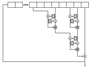
Two buffers, each containing room for 256 bytes, are filled by generating bytes from the first and second strings by placing them in a nonlinear shift register.
The form of that shift register is shown in the following illustration, showing its precise form for the first string, with the exception that S-box S3 is shown, as used for most ciphers in the Quadibloc series, rather than S7 as used in Quadibloc 24.

Five bytes are read from the string at each step. For the first string, they are, as shown in the diagram, the eighth-last, fifth-last, third-last, and second-last bytes and the last byte. For the second string, they are the eighth-last, seventh-last, fourth-last, and second-last bytes, and the last byte. For the third string, they are the twelfth-last, tenth-last, seventh-last, and fourth-last bytes, and the last byte.
Each time the shift register produces a byte, it does so as follows:
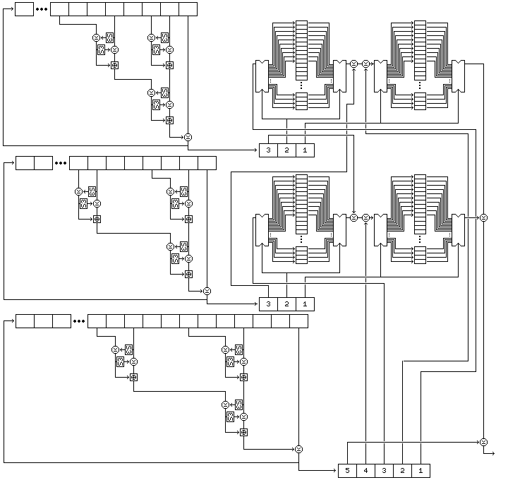
The cipher uses four buffers, each of which contain 256 bytes. The first buffer, called buffer A, is filled with 256 successive bytes generated from the second string by means of the nonlinear shift register filled with the second string, and then buffer C is filled with another 256 bytes generated from the second string. The second buffer, called buffer B, is filled with 256 successive bytes generated from the first string by means of the nonlinear shift register filled with the first string, and then buffer D is filled with another 256 bytes generated from the first string.
The whole of the subkey byte generation procedure is as illustrated in the diagram below:

Note that the positions of the buffers A through D in the diagram above are as follows:
C A
D B
and the course of subkey byte generation is the following:
To generate bijective S-boxes, which in the case of this cipher are the S-boxes S8 and S9, the following procedure is used:
The resulting contents of buffer D are used as the key-dependent bijective S-box intended to be produced. Note that this is a procedure, introduced for Quadibloc X, is more straightforwards than the other two basic procedures used previously to produce S8 in ciphers in this series prior to Quadibloc 2002E.
This procedure, although it uses buffers A and B, leaves them undisturbed; thus, byte generation may continue after one S-box is produced.
The subkey generation procedure given above works well for keys from 64 bits to 1,024 bits in length. When the length of the key approaches 2,048 bits in length, however, the first two shift registers are no longer thoroughly mixed by filling the buffers initially.
Thus, the following modified subkey generation procedure is given for keys which are more than 1,024 bits long. A key must still be a multiple of 32 bits in length.
This method ensures that the key schedule is a function of the entire key.
Next
Start of Section
Skip to Next Chapter
Table of Contents
Main Page