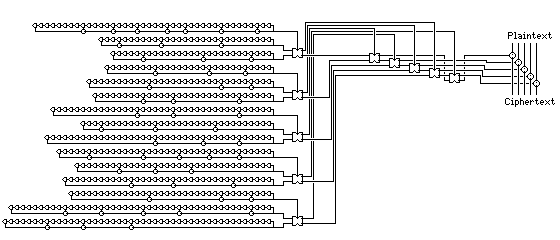
Since many of the early electronic cipher machines were used as telecipher machines, it is possible they were designed around generating five bits in a single cycle in parallel. A possible very simple design of that type is illustrated below:
Here, five Geffe generators produce five bits. But the five unused shift register outputs, instead of being discarded, are used to control swapping the five Geffe generator outputs. Note that the unused bit from one Geffe generator is always used to swap the two outputs of two other Geffe generators (at least if no preceding swaps take place).
Since electronic circuitry is much faster than the mechanical components of teletypewriters, however, a design like the above will not be considered for long before the idea of running it five times faster, and producing a serial bitstream from its output, is considered:
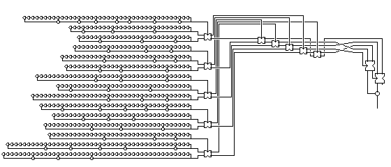
Since the circuit that takes five bits of input, and produces one bit of output, involves some swaps of adjacent input bits, and the device producing those five bits also swapped adjacent bits, the order of the bits has been shuffled before the last combining circuit, so that swaps of bits not previously subject to exchange will take place instead.
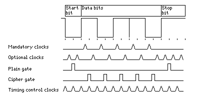
When the signal from a teletypewriter is in serial form, it is accompanied by stop and start bits; the idea might occur to a cipher machine designer to use this as an opportunity for an extra complication; another shift register could control whether, during the stop and start bits, when the machine's output is not XORed with the communications signal, the device is clocked. Since the start and stop bits take as much time as two and a half data bits, 0, 1, or 2 clock ticks could take place without any increase of speed. Double the speed of the device (and, of course, a tenfold discrepancy between electronic and electromechanical devices is far from unreasonable), and the opportunity arrives to have either 1 or 2 clock pulses between the data bits in a single character as well.
When this fairly simple stratagem of designing a cipher machine around the characteristics of 5-level code signals is illustrated by a timing diagram,
along with a block diagram, illustrating the use of each of the timing signals,
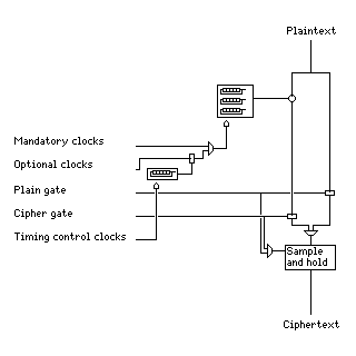
(the box with three shift registers in it represents the apparatus with five Geffe generators whose output is combined to produce a single output bit shown above) it looks quite complicated.
Other constructs, instead of Geffe generators, could be used to generate the bitstreams the device starts with, more than one extra clock pulse for optional clocks could be used per baud, and, perhaps most important, instead of clocking, or not clocking, all fifteen shift registers in the cipher assembly during an optional clock pulse, one could instead use more than one tap, or more than one shift register, to control the clocking of the various shift registers independently during the extra time periods.
Various references have noted that the early electronic cipher machines were often of a self-synchronizing nature. Also, the SKIPJACK block cipher design was described in the document revealing its design as a kind of shift register, suggesting how a shift register could be used for a simplified form of block encipherment. Taking these ideas together, one arrives at the following illustrative diagram:
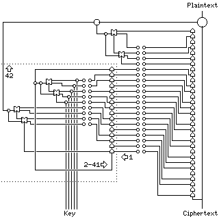
This diagram is scaled down. On the right, the basic characteristics of a self-synchronizing cipher are shown: a shift register without feedback stores the last several ciphertext bits. A nonlinear function of these bits, which can be varied by a plugboard, is used as the keystream which is XORed to the plaintext to become the ciphertext.
Such a design, in itself, would have to be made extremely elaborate, with a very large number of logic gates, to offer any security. On the right half of the diagram is shown how, with a limited number of gates, using a shift register to do block encipherment, more security might have been obtained.
The area enclosed by dotted lines is clocked differently from the rest of the diagram. It produces a bit to be XORed with the plaintext by a process that has to be described; it can't be easily shown in the diagram. An attempt has been made, though, with arrows showing the order in which the paths shown in the diagram are used. First, the bits of old ciphertext are loaded into the feedback shift register inside the dotted lines; the entire register is filled from the outside. This takes place during cycle 1, as indicated by the first arrow. Then, the feedback shift register is cycled several times through its entire length. This register is shown as being stepped 40 times, during cycles 2 to 41; since the shift register contains 16 cells, the bits in it cycle more than twice through its whole length. The final state of the register is then used to produce the output bit used to XOR with the plaintext, by means of another nonlinear function. This output is taken at the last, during cycle 42.
Note that the state transition function of the feedback shift register is invertible; the oldest bit of it is XORed to a nonlinear function of five other bits before being recycled. This is invertible for the same reason that a Feistel round is invertible; the five inputs to that function are only moved, not changed. This doesn't guarantee a long period, but it does mean that after any fixed number of cycles, each different initial state will result in a different final state. This means that there is no possibility, despite the fact that the shift register has nonlinear feedback, and therefore many of its properties are hard to understand, that after some large number of cycles a large number of different initial states will lead to the generator winding up in the all-zero state (or some other degenerate condition) and getting stuck there.
In other words, the state space is incompressible under the state transition function provided by a nonlinear shift register with the property that the eldest bit is not altered, and is XORed with the output in the last stage of calculating the output. (The usefulness of setting up a nonlinear shift register in this way was in fact briefly noted in Applied Cryptography, where it is stated that the danger of its sequence dying out to all zeroes can be "easily cured".)
The nonlinear function applied to the final state includes the newest bit in the shift register as one of its inputs, so that none of the cycles the shift register went through to produce that state is wasted.
The arrangement of the two plugboards in the diagram is one part of the key; in practice, something less messy than plugboards would have been used, but not worrying about such details leaves the diagram simple. Another place where key material is used may be during the stepping of the fast feedback shift register, which may be fed one character of a 40-character key during that stepping.
With known plaintext, if the first shift register, the one without feedback that simply stores old ciphertext bits, is short, a codebook attack on the cipher is possible as a direct consequence of its self-synchronizing nature. That is, one could make a table of the possible values of the preceding N ciphertext bits, for increasing N until N reaches the length of that shift register, and find that for each entry, whether the current plaintext bit is inverted or not is consistent.
It may be noted that this arrangement, although it is greatly simplified, is essentially a scaled down version of operating a block cipher in Cipher Feed-Back mode, with the addition that the "block cipher" output is further condensed by a nonlinear function of several of its bits.
Although the correlation attack is primarily a problem for designs based on linear-feedback shift-register outputs, the decorrelation circuit met on the previous page can be combined with this form of design as well. Thus, the block-cipher like stage can generate two bits of output, one which is decorrelated, and one which controls the decorrelation. It should be noted, of course, that it takes a number of cycles for this type of decorrelator to be filled with output bits, particularly as the random control of which shift register is filled can mean the time required is variable. Special circuitry to enable an initial fill mode is possible, just as in the MacLaren-Marsaglia random number scheme, the buffer is initially filled with a number of consecutive PRNG outputs.
More elaborate constructs are also possible, like the one below:
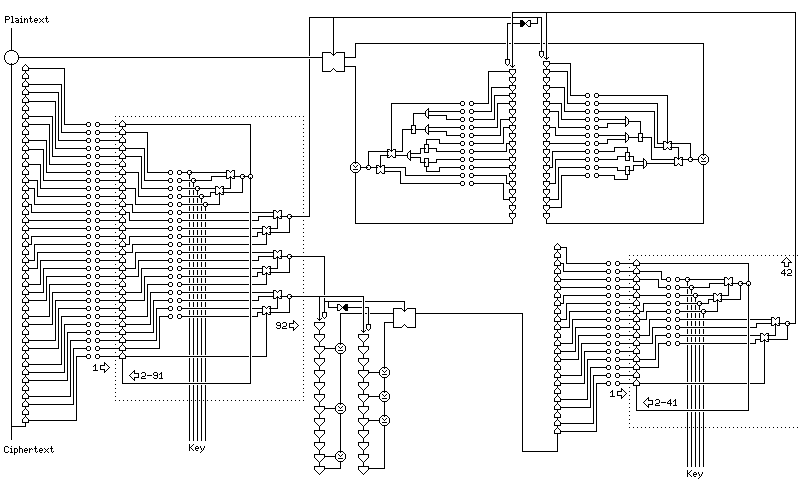
Here, 30 bits of previous ciphertext are cycled three times through one nonlinear shift register with an incompressible state space, and three bits of output are produced. One bit is fed into a decorrelator, the second controls the decorrelation, and the third is used for another decorrelator later in the circuit.
The decorrelated output is again fed into another block-cipher like nonlinear shift register, this time one which acts on a 16-bit block, as in the previous example. The output of that stage is decorrelated under the control of the third bit used earlier. Here, however, instead of the decorrelator simply XORing together multiple old output bits, a nonlinear function of old output bits is XORed with the one being shifted out of the shift register being clocked, making this a nonlinear decorrelator. The five-input nonlinear circuit that I have used throughout these examples is expanded by making one of its inputs the OR of two ANDs, and another the AND of two ORs; thus, the significance of the bit that chooses between these two somewhat biased values is increased.
This rather daunting diagram changes to the following
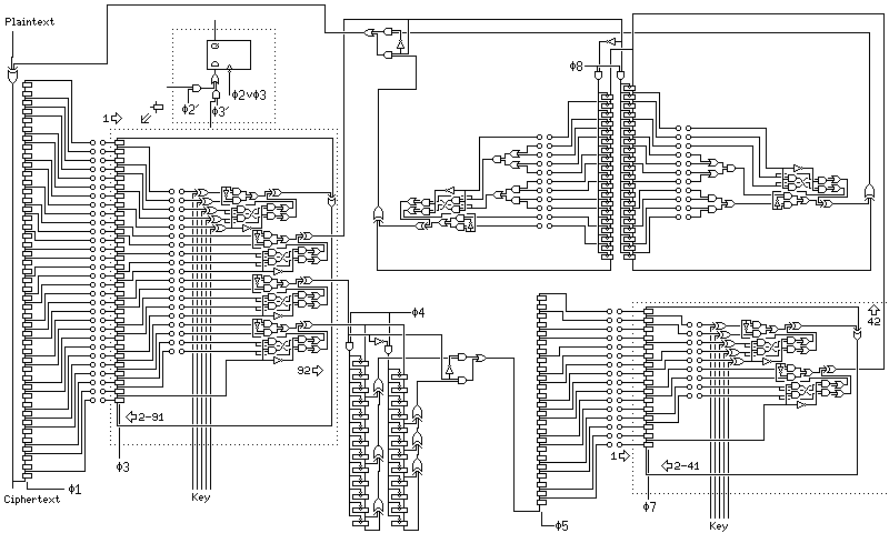
when drawn with standard logic symbols. Of course, since I wished to avoid increasing the size of the diagram, the shift-register flip-flops are not drawn explicitly. The arrangement involving the shift registers shown as clocked by phase 3 and phase 7 is somewhat involved, and so an inset for the one clocked by phase 3 shows what is actually going on for each flip-flop in the shift registers. Essentially, phase 2 clocks loading the entire register from outside, and phase 3 steps the register. Type D flip-flops are shown as being used to build the shift registers for simplicitly, even if in practice type S-R flip-flops would be used for economy.
Also, in this diagram, it is necessary to make explicit the timing signals used; the following chart:
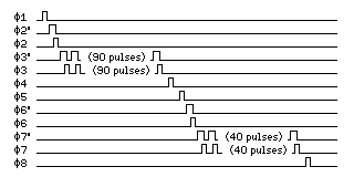
shows what those signals are.
The leading edge of the phase 1 signal must occur at some time when the previous ciphertext bit is valid; after the trailing edge of the phase 8 signal, the output of the ciruit is valid, so the new ciphertext bit will be valid when the new plaintext bit is valid.
Until such time as the cipher machines of the 1970s become declassified, these imaginative reconstructions of mine may perhaps prove useful to spy novelists wanting to insert authentic-looking cipher machine plans into their works.
When the real thing is revealed, of course, it will be far more secure than my careless effort. I think my first diagram, the one based on the Kinetic Protection Device, is likely to be rather more elaborate and complicated than anything actually used, while the first of the two designs shown on this page, showing five Geffe generators, is probably more straightforwards and simple than anything actually used. As the second one is based on various public comments concerning the electronic cipher machines of the U.S. during that period, although it is scaled down, it may illustrate a principle that had actually been used, or, of course, one that we are intended to think was used. In that case, the "real thing" would have had longer shift registers, and more complicated nonlinear functions (and three different ones) than my simple improved Geffe generator which I used three times in the diagram. Also, there may have been an attempt to encipher the five bits of a teleprinter character in parallel. It should also be noted that, for purposes of the illustrative diagrams on these pages, I have not troubled to ensure that all the shift register polynomials used are actually of maximal period, which would be required in practice.
Next
Chapter Start
Skip to Next Chapter
Table of Contents
Home Page