In this chapter, we have seen some examples of rotor machines with very irregular rotor movements.
The SIGABA achieved very irregular rotor movement by a uniquely strong method, using the changing jumbled maze of wires in a part equivalent to a complete conventional rotor machine to supply electrical signals controlling the seemingly random stepping of rotors in what amounted to a second conventional rotor machine for enciphering the letters of the text.
The Swiss NEMA cipher machine achieved irregular rotor movement by accompanying each rotor with an adjacent rotating ring, which had notches on it that inhibited that rotor's movement. The rings always moved, except for two rings that were sometimes prevented from moving by a second set of notches on the first rotor's ring.
Also, U. S. Patent 4,143,978, filed on May 4, 1938, but only issued on March 13, 1979, with inventors Bern Anderson and Donald J. Seiler, describes a machine which made use of five pinwheels with 25 positions to control the five rotors with 26 positions. This patent is for the ECM Mark III. Despite its higher number, this design preceded the ECM Mark II, also known as the SIGABA.
And, of course, the Enigma A and Enigma B had a very irregular rotor movement at the dawn of the rotor era, by having each rotor controlled by its own cam, and each cam having a number of positions relatively prime to all the others. Had the cams been resettable pinwheels, the design would have been quite impressive indeed.
Descriptions of a later rotor machine suggested to me as one possibility (another is that it might have more closely resembled the ECM Mark III, although with important differences) that it might have achieved irregular rotor stepping based on a principle we will see later in the descriptions of the Siemens T-52d and T-52e Geheimschreiber telecipher machines:
Given three or more pinwheels or cams, each of which produces a sequence of binary bits as it rotates, bits from each pinwheel (perhaps sensed at a different position on the cam than the bits used for the purpose of encipherment) could be used to control the movement of other pinwheels.
Although this seems like a compromise of the potential security of a rotor machine, using the rotors to step themselves instead of having a separate set of pinwheels or cams to control stepping has the major advantage of making it simpler to set up the machine for an encipherment.
But if one tries to do this in the simplest way, just using one pinwheel to cause another to step, what is there to prevent all the pinwheels from coming to a position where they are producing a zero value for their stepping output, so that they will all stay in one position thereafter?
The Siemens Gehemschreiber prevented this by a scheme that looked something like this, illustrated with five cams labelled A, B, C, D, and E:
A steps if D or (not E)
B steps if E or (not A)
C steps if A or (not B)
D steps if B or (not C)
E steps if C or (not D)
In this illustration, the output from each cam forces the stepping of one other cam, and the complement of that output forces the stepping of a third cam. This ensures that some stepping will always take place.
In this case, as the bits from the cams are also used to encipher a binary signal by being XORed with it, active and inactive positions on the cams need to be close to equal in number. Since each cam steps based on the OR of two inputs, this means that the cams step about 3/4 of the time.
Since outputs from those cams are used for encipherment as well, they should step almost all the time. While occasional failures to step can make the bit sequence irregular, bits that do not change also allow plaintext patterns to be visible.
The Lorenz Schlusselzusatz, which used two sets of five pinwheels, one which always moved, and another set which moved, or remained still, in unison, half the time either way, based on a more conventional scheme involving control from two other pinwheels, was cryptanalyzed with the aid of the early electronic calculating device COLOSSUS partly because the patterns of the constantly moving pinwheels were visible when the other ones did not move. (The fact that 5-level teleprinter code is designed so that 0 bits strongly outnumber 1 bits, to prevent mechanical wear and tear and to make paper tape less fragile, also was an important factor.)
In a rotor machine, however, moving even one rotor completely scrambles the cipher alphabet it provides. If each rotor moved with probability 1/2, then each new alphabet would be from the largest and most uncertain possible set of alternatives.
Could the principle used in the T-52 be modified to produce movement with probability 1/2, and yet still ensure continual movement which will not cease to involve any of the rotors?
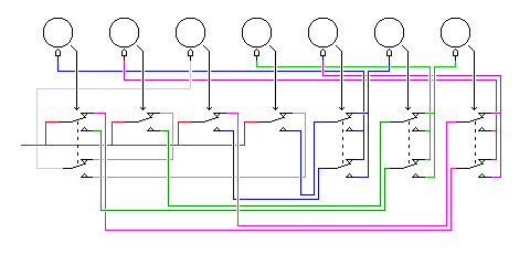
The first scheme I came up with to do this is illustrated by the following diagram:

It may be easier to understand with the diagram shown below and to the right:
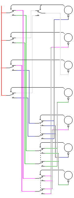
Using seven rotors in this example, I first start with four live inputs, which are turned into eight outputs having a 50-50 chance of being live by being redirected by the active teeth on four of the rotors.
This is shown in the diagrams above and to the right by a red wire, carrying a live input from the power supply, being switched to four of eight wires by four switches, each controlled by a rotor. In the diagram to the right, this is the first layer of the circuit, shown in the leftmost column.
Then, six of these eight signals, in pairs from different rotors, are swapped (or not) under the control of three other rotors.
One of the two remaining signals is selected by means of an extra pole in the switch under one of the first four rotors.
The swapping and the selection is always done under the control of a rotor which was not involved in determining if either signal used as input was live. The color scheme in the diagrams is chosen to make that clear. In the diagram to the right, this is the second layer of the circuit, shown in the middle column.
The seven output signals then control the stepping of the rotors. Again, as the colors help to make visible, each signal is directed to a rotor that had no part in its creation, in either the first or the second layers.
With reference to the color scheme in the diagrams:
Green: Two signals controlled by rotors 1 and 2 are then swapped under the control of rotor 6. The two resulting signals control the movement of rotors 4 and 7.
Dark Blue: Two signals controlled by rotors 3 and 4 are then swapped under the control of rotor 5. The two resulting signals control the movement of rotors 1 and 6.
Purple: Two signals controlled by rotors 1 and 3 are then swapped under the control of rotor 7. The two resulting signals control the movement of rotors 2 and 5.
Gray: Two signals controlled by rotors 2 and 4 then have one signal selected from them under the control of rotor 1. The resulting signal controls the movement of rotor 3.
This basic principle, with little change, would work with any odd number of rotors, starting with five.
The specific arrangement in the diagrams shown above was selected to minimize wire crossings in the original (horizontal) diagram, so that it would be as legible as possible, and, with the rotors labelled in order from left to right as A, B, C, D, E, F, and G is:
A steps if        (D and E)       or        (C and (not E))
B steps if  ((not C) and G)       or  ((not A) and (not G))
C steps if  ((not D) and A)       or  ((not B) and (not A))
D steps if        (B and F)       or        (A and (not F))
E steps if  ((not C) and (not G)) or  ((not A) and G)
F steps if        (D and (not E)) or        (C and E)
G steps if        (B and (not F)) or        (A and F)
where the control signal different from the others is the one stepping rotor C.
Since we start with eight signals, four of which are active, and swap them in pairs, only in one case selecting only one of two signals to use, half the time four rotors will advance, and the other half of the time three rotors will advance.
With an even number of rotors, of course, the same principle could be applied even more simply, without the need for one control signal to be different from the others.
But many other arrangements are also possible. An arrangement based on a slightly different principle is shown here:
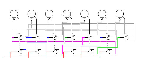
Here, each rotor is controlled by the OR of the AND of two independent inputs, so, based on each rotor having half of its teeth present and half of them absent, causing each signal and its complement to be active half the time, the chance of any one rotor moving on average is 7/16 rather than 1/2.
We start by creating seven signals. To ensure that at least one rotor will always move, two of them are the signal from one rotor and its complement; the other five are the signals from five other rotors.
Then, we change these seven signals into fourteen signals, by switching them to one of two destinations, and the output from each of the seven rotors is used to perform one such switch.
Finally, the wired-OR of two of these signals controls one rotor that had no direct part in creating it.
Here, from one to six rotors will always move, creating more possibilities for the next rotor position. However, as we will see at the start of the following chapter, a 3 out of 7 code contains 35 entries, so with seven rotors rather than five, having only 3 or 4 rotors move each time already creates more than twice as many possibilities as are needed.
The actual arrangement in the diagram shown, again chosen for clarity, with the rotors labelled as A, B, C, D, E, F, and G from left to right, is:
A steps if       (B and D) or       (E and (not G))
B steps if       (C and E) or       (F and (not A))
C steps if       (D and F) or ((not A) and (not B))
D steps if       (E and G) or       (A and (not C))
E steps if       (F and A) or       (B and (not D))
F steps if ((not A) and B) or       (C and (not E))
G steps if       (A and C) or       (D and (not F))
While these arrangements will certainly produce rotor movements that seem jumbled and unpredictable, it is not immediately clear how long the period of such rotor motions might be; it might be only a few times larger than the number of positions on a rotor.
Here is an example of a slightly more complicated setup, based on the same general principles.
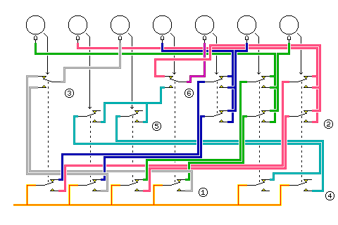
Essentially, the wiring is the same as the first example, (although the ordering of the connections has been changed slightly, as indicated by the reversal of the colors green and blue in one portion of the diagram) but in addition, one signal is created using the scheme in the second example, and a switch controlled by rotor 4 determines whether that signal, shown in dark green, or the normal signal following the pattern of the first example, shown in purple, is fed to rotor 5.
The sections of the diagram have been labelled.
The first three sections show the switches which operate as in the first example.
Section 1 shows the four switches which, given the live signal as input, produce eight outputs, four of which are active.
Section 2 shows six switches, wired so as to swap three pairs (shown by blue, green, and purple wires) of signals from the first four switches.
Section 3 shows one switch, which selects between the two remaining signals from the first four switches to provide the seventh output signal.
The next two sections show the new wiring which creates an alternate signal that can be used to step rotor 5, following the principle shown in the second example.
Section 4 shows two switches, fed the live input, which produce two outputs, each of which may be active or not.
Section 5 shows two switches, fed those two outputs, producing two outputs which are only have as likely to be active, and which are then joined by a wired-OR.
The final section selects the signal to use to advance rotor 5.
Section 6 shows one switch, which selects between the output from section 5 or one of the outputs from section 2.
Again, labelling the rotors from left to right as the letters A through G, the logic of the wiring in the diagram is equivalent to:
A steps if   ((not D) and F)       or  ((not C) and (not F))
B steps if         (C and G)       or        (A and (not G))
C steps if         (B and (not A)) or        (D and A)
D steps if   ((not B) and E)       or  ((not A) and (not E))
E steps if ((      (C and (not G)) or        (A and G)      ) and (not D)) or
           ((((not F) and B)       or        (G and C)      ) and D)
F steps if   ((not B) and (not E)) or  ((not A) and E)
G steps if   ((not D) and (not F)) or  ((not C) and F)
Note that the signal controlling the stepping of rotor E is a function of whether an active or inactive tooth position is found on all six other rotors.
One could even use, with a suitable rearrangement of rotor assignments in one case, the complete wiring arrangements of both the first and second examples, with their outputs connected together in a wired-OR, and a single switch controlling whether the live input goes to the first or second circuit. However, even if the first or second examples would prove too simple, such a drastic remedy should not be required. Instead, the example above should be sufficiently complex to correct the problem, because although only the stepping of rotor 5 (or E) is made more complex in this example, it in turn affects the stepping of all the other rotors.
Other arrangements, based on the more conventional scheme of moving rotors like the wheels on an odometer, which guarantees the maximum possible period, could be produced which also result in a fairly irregular movement of the rotors.
Incidentally, before proceeding, it is very important to
clarify the difference between the situation which I have denoted
in my schematic diagrams by
![]() and the situation which I denote by
and the situation which I denote by
![]() in a diagram. In the first case, a tooth on one rotor causes
another rotor to move only once, when the first rotor moves into
the position distinguished by that tooth. In the second case,
a tooth on one pinwheel, or cam, or even a rotor, causes the next
one to move with the encipherment of each letter for as long as
the first pinwheel remains in the position associated with that
tooth.
in a diagram. In the first case, a tooth on one rotor causes
another rotor to move only once, when the first rotor moves into
the position distinguished by that tooth. In the second case,
a tooth on one pinwheel, or cam, or even a rotor, causes the next
one to move with the encipherment of each letter for as long as
the first pinwheel remains in the position associated with that
tooth.
While the first type of movement is usually accomplished mechanically, the control rotors of the SIGABA and the rotors of the M-228 and M-229 moved this way under electrical control. The second type of movement seems like an obvious consequence of electrical control: a wheel that is in different positions turns a switch on and off depending on what position it is in. So how can the first type of movement also be electrical?

This diagram illustrates the difference between the arrangements required for the two types of motion. The large teeth shown in green correspond to the 26 normal positions of the rotor, where a tooth may be either present or absent. The small teeth shown in red are located between rotor positions, so that a tooth, if present, will move across the sensing position as the rotor advances from one position to the next.
For the first type of motion, pulses occur when the rotor that is their source is moving, and so it is reasonable that another rotor would move when a pulse of electricity is switched on. Making a rotor move only one step per pulse seems like only a small mechanical detail.
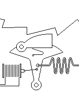
For the second type of motion, instead of an elaborate approach involving storing the signals sensed from the rotors in a buffer, what is necessary is, first of all, that the live inputs to the circuit are actually timing pulses, and, so that the rotors will not move while their positions are being sensed, rotors should move just after the trailing edge of a pulse. This can be achieved by having the pulse go through a solenoid, pulling a lever back which is then restored to its original position by a spring after the pulse ends, with a rachet mechanism causing the lever to advance the rotor it controls only on its return journey: this is a very common and standard mechanical arrangement, illustrated in the diagram at left. Since the device also supplies a gentle push to the sawtooth gear when moving in the "wrong" direction, a conventional ratchet mechanism, which is not shown in the illustration, is also required to keep that gear moving only one way (although in some cases, friction may be sufficient).
For the other case, the same mechanical arrangement could be used, although in that case, having the rotor advance on the leading edge of the pulse would be appropriate, as it would avoid unnecessary delay. This would involve reversing the positions of the electromagnet and the spring in the diagram above, and in that case, the spring would not have to be as strong, since it would only return the mechanism to position instead of also having to push on the gear. A similar mechanism, rather than a small motor, is likely to be found in those quartz clocks and quartz watches that have hands instead of a numeric display.
Since this was written, I have learned that this web page now contains a full description of the KL-7 rotor machine, which did indeed use the second type of rotor motion for its seven moving rotors.
Initially, I had been daunted by its complexities, and did not include a description on this page, but recently I accidentaly stumbled on this similar page on another site, and decided it was time that I should do so.
Here is a diagram of the KL-7 following my usual conventions:
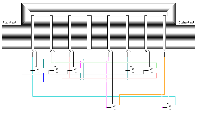
The design is simpler than my imaginary designs above; there is only one SPDT switch per rotor, and no attempt is made to make the frequency of rotor motion exactly 1/2, assuming that half the positions on the rings around the rotors are raised.
The five switches in the top row, which sense raised positions on the rings for rotors 1, 2, 3, 5 and 6 (the stationary rotor between rotors 3 and 4 does not get a number) recieve a constant voltage as input (actually, that voltage is switched off if the machine is set to pass through plaintext instead of enciphering, but these details are not shown on my simplified diagram).
They produce signals which directly cause rotor stepping according to the following scheme:
Rotor 2 steps if ( not (5) ) OR ( not (6) )
Rotor 3 steps if       (6)   OR       (2)
Rotor 4 steps if ( not (2) ) OR ( not (3) )
Rotor 5 steps if       (3)   OR ( not (1) )
Rotor 6 steps if       (1)   OR       (5)
where (5) means 'the position currently sensed on the ring around rotor 5 is raised'.
The two switches in the bottom row recieve as their input signal the same signal that is used to advance rotor 4, and they control the movement of rotors 1 and 7.
So the result of their operation is:
Rotor 1 steps if ( not (7) ) AND ( not (2) ) OR ( not (3) )
Rotor 7 steps if ( not (4) ) AND ( not (2) ) OR ( not (3) )
Note that rotor 7, which has a more complicated motion because three inputs are involved, is one of those that control the motion of rotor 1, giving it an especially complicated movement.
Now that this is clarified, let us examine a more complicated design based on the first type of rotor motion.
Instead of having just one notch or tooth on a rotor, any number of teeth that is relatively prime to the number of positions on the rotor, if used in an odometer-style arrangement, would still produce a maximal period, since when one rotor returns to its original position, the rotor it advances will be in a spot from which it will only return to its original position at the same time that the rotor preceding it returns to its original position after being advanced 26 times if it is a 26-position rotor, even if it has also passed through its original positions at different times several times before then.
Another thing that would not interfere with a maximum period would be for a rotor participating in such an arrangement to also be advanced any number of times for each revolution of a rotor which preceded the rotor directly controlling it. All such advances would ultimately cancel out, being a multiple of 26 or other rotor size, over a full revolution of the rotor immediately preceding the rotor.
I would diagram such an arrangement in this fashion:
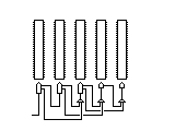
One important thing, to avoid problems with a mechanical version of this design, and to ensure that maximum period is achieved, is that the teeth used to advance a later rotor must never be in the same position as the teeth used to advance the next rotor.
Of course, to achieve both a guaranteed long period, and a more irregular sequence of motions, one could combine both types of rotor motion, the first type, or transition-driven advance, and the second type, or state-driven advance, in a single design.
Thus, we might have two groups of rotors, ABCDE and GHIJK, which are connected for state-driven advance, and in addition, rotor E might drive rotor F, and rotor F might drive rotor G, using transition-driven advance.
Is it possible to combine a guarantee of long period with irregular rotor movement from the same source? Obviously, one could use five cams to produce an irregular motion, and another five cams to produce motion with a period equal to the product of their lengths. But can things be arranged so that the period is guaranteed to reflect all the items used, and yet the motion is irregular as well? Already, we've seen in my example of a transition-driven design with extra further forward carries one way to do this, but while the period is guaranteed, the motion is only irregular to a limited extent.
Would the SIGABA have a guaranteed period of 26 to the tenth power if it were modified as shown in this diagram:
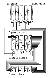
Here, all ten of the rotors are shown as being advanced by a conventional rotor mechanism, in addition to the cipher rotors being advanced by the unique control signals of the SIGABA. Instead of showing an OR gate controlling input to the rotor stepping mechanism, two separate symbols for rotor advance are shown, one behind the other. This indicates that, to ensure maximum period, I think it would be necessary to use different clock phases for the two types of rotor advance, so that it would be possible, if both systems of rotor advance would cause a rotor to advance, for that rotor to step twice. However, when one rotor advances due to a control signal, it would also have to cause conventional carries. But this separation of phases would then occur without (a certain kind of) special effort, since the control rotors cannot be moving when the cipher rotors are moving in response to the control signals which have passed through their wiring.
One way that it seems obvious it is safe to combine transition-driven and state-driven rotor advance would be through something like this:
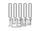
Here, superimposed on a conventional transition-driven odometer-like rotor advance, earlier rotors are also driving later rotors, further down the chain, but based on their state, not on transitions. Again, it seems that over a full cycle of transition-driven advances, the extra state-driven advances should cancel out, not affecting the overall period, even if they provide additional movement in the interim.