Also on the Crypto Museum web site is a description of the Gretag TC-53 cipher machine.
I had heard of the Hellschreiber machine, which transmitted letters by their shape rather than a code. In addition to the well-known 7-segment displays used by many pocket calculators, occasionally a 16-segment display was used for alphanumeric characters. A unique teleprinter design based on 16-segment characters, but using some of those segments in combination, so that there were only thirteen actual portions of the character to activate, plus a fourteenth bit for a character that could not be constructed in this way (partly because of a technical limitation of the device, so that no more than five of the character elements could be used at once, due to the use of some parts from conventional teleprinters), was what this cipher machine worked with.
For the moment, I will not attempt to go into the details of the plaintext character set this machine enciphered; the fascinating details of that are on the Crypto Museum web site. Also, the version made for the Swiss Army had a circular indicator, with the letters from A through Z followed by the letters A E I O U Y repeated, which used a series of five disks, each of which could be moved to a shifted position by solenoids, that could display a letter from an input of five bits - this was used so that the machine could assist in randomizing the indicator settings for each message; I will skip going into detail about that as well for now.

In any event, the machine had eight wheels which were like two pinwheels of the same size stuck together. However, active positions were changed to inactive by permanently breaking off a tooth from the wheel. These pinwheels each had 26 positions on them to simplify key setting; for this detail, I am indebted to the web site of Jerry Proc. Note that this means that it is not possible to remove the teeth in an "ideal" pattern, where not only are exactly half the teeth removed from each pinwheel, but equal numbers of remaining and removed teeth on one pinwheel are next to the teeth of each type on the opposite pinwheel on the same wheel, since there are four possibilities, and 26 is not divisible by four.
These wheels were stepped in an irregular fashion. The presence or absence of a tooth was used to invert a bit that started with a constant value. Sixteen values were produced, since the bit was XORed in turn with each of the two bits from each wheel, and then that was expanded to 32 by using each bit and its inverse.
Something equivalent to a plugboard was apparently used to select 26 of the bits so generated (from 30 of them; the internal wiring of the machine skipped two of those possibilities), although no plugboard or dials performing a similar function are visible externally from the unit, and they went into a set of five standard 26-contact rotors to be rearranged.
Then the 26 bits so produced were used for three different things:
Four of them would then control the stepping of the four rotors for the next character. (This required temporary buffer storage in relays.)
Eight of them would be used to control the stepping of the eight wheels we started with. (This also requires the buffer storage.)
The remaining fourteen bits would be XORed with the plaintext in its unusual fourteen-bit code.
So far, it looks like this machine, while producing a highly secure cipher, might have one problem. There might be one chance out of 4096 that neither the four rotors nor the eight keyweels would move, and then the machine would be stuck.
However, this apparently would only be the case if eight switches which controlled how the keywheels stepped were all in one of the two possible positions, leading to the rotor output controlling their stepping.
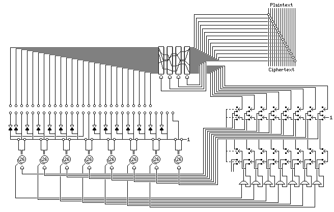
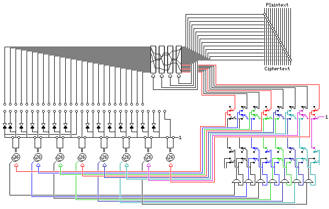
A complicated circuit, which I hope to have depicted in conformance with the available circuit diagrams for the machine, provided eight switches, which would select between each keywheel being controlled by one of the bits of rotor output, or by a bit from one of the other keywheels, picked off at a different point than that used for the main encryption.
However, this diagram, showing one particular position for the switches, should help in making sense out of how that circuit works.

As with an odometer, the keywheel that has the simplest motion, which we will consider to be the first one, is on the right, and so are the switches that control it.
The leftmost switch is shown in what the diagram shows as the down position. The result, as far as the stepping of the first keywheel is concerned, is simple. It is stepped by the associated output from the rotors. The rotor signals which are connected to step their corresponding keywheels are all shown in red in the diagram.
The second switch is shown in what the diagram shows as the up position. Here, the signal sent to the second keywheel is taken from what the first switch has passed through, an always-on signal indicating that the keywheel is to step for every character enciphered. This signal is shown in purple.
The third switch is also up. Since the second switch is up, it does not pass a signal through; instead, the signal from the alternate tap on the second keywheel is taken and used to step the third keywheel. However, there is also a logical OR gate; so the signal used for stepping the fourth keywheel is ORed with the signal from the alternate tap on the second keywheel to produce the signal that steps the third keywheel.
Physically, the keywheels were in the opposite order, from right to left, in the actual machine than as shown in the diagram. The "down" switch setting, which selects moving a keywheel based on rotor output, is called "closed", and the "up" switch setting, where the alternate tap of one keywheel moves another, is called "open"; it appears that the switches are in a neutral position for closed, and are flipped upwards for open.
It was noted above that the number of positions on a keywheel is not divisible by four, preventing the absolute minimization of bias and correlation.
Given that the keywheels are used to control stepping, however, there are other considerations that are more important. After all, Converter M-228 provided a secure cipher by putting a constant input through a series of rotors.
If the keywheels were controlled in an odometer-like fashion, then the side of the keywheel that is tapped for controlling keywheel motion would need, for maximum period, to have a number of active teeth that is relatively prime to 26. On the other side, though, having exactly thirteen active teeth to minimize bias would be acceptable and presumably desirable.
Since the keywheels are fixed in the machine, not subject to being re-ordered, the one shown on the left in the diagrams here would be an exception to this; its teeth, never being used to control keywheel motion, would not need to follow this rule, and there could be thirteen active teeth on both of its sides.
However, the device has the other type of motion; a given keywheel continuously advances when the one preceding it is statically active, rather than advancing once as the preceding one enters or leaves an active state. And then there is the effect of the OR from the preceding keywheel.
Incidentally, while I was quite aware of the association of Gretag with cipher machines, from seeing advertisements for their later Gretacoder, I was not aware that the company - in a separate division - also manufactured an item which gave it an even greater claim to fame, the Eidophor.
Before Texas Instruments developed micro-mechanical integrated circuits with small tilting mirrors for projection televisions and monitors, techniques for projecting video, or even film, on screens had limitations which limited the size of the screen which could be filled with a bright image.
Celluloid could catch fire or explode, so it quickly gave way to "Safety Film" made from transparent plastic made from petrochemicals, but even that could easily melt in a projector that became too hot; video projection from CRT tubes was limited because while the display on a projection CRT could be made somewhat brighter than what we are familiar with from direct-view cathode-ray tubes, a cathode-ray tube was not a brilliant light source like an arc lamp or even an incandescent bulb.
The Gretag Eidophor overcame these limitations through a unique and little-known technology; an electron beam disturbed a thin film of oil on a mirror, which allowed controlling a very bright beam of light in brightness at each part of an image. It was used for the analog projection of theatrical movies by means of high-resolution video, and it was used by NASA in Mission Control.